


How to Choose a Cabinet Cooling Fan for Dusty Industrial Enclosures
Industrial control cabinets often contain heat-generating components such as PLCs, variable frequency drives (VFDs), power supplies, and automation controllers. In dusty production environments, maintaining suitable internal temperatures can be difficult because the cooling system must manage both heat and airborne contamination.
A cabinet cooling fan can remove heat by bringing cooler ambient air into the enclosure. However, adding a dust filter also increases airflow resistance, and that resistance may rise as the filter accumulates particles. A fan that appears sufficient based on its catalog airflow rating may therefore deliver less cooling air after installation.
Selecting the right solution involves three decisions: whether forced ventilation is necessary, whether ambient air can safely enter the enclosure, and which fan configuration can maintain sufficient airflow under the actual operating conditions.
How Do You Choose a Cabinet Cooling Fan for an Industrial Control Panel?
The selection process should begin with the cabinet's heat dissipation, ambient temperature, contamination level, and enclosure protection requirements. These factors determine whether filtered ventilation is appropriate before any fan model is considered.
Not every control cabinet needs a continuously operating fan. A lightly loaded PLC enclosure may dissipate sufficient heat through its surfaces, while equipment containing VFDs or power converters may require forced-air cooling.
Adding unnecessary ventilation can increase maintenance requirements and introduce another potential path for dust to enter. The decision should therefore be based on actual thermal conditions rather than an assumption that every electrical panel needs a fan.
Check Whether Filtered Ventilation Is Suitable
Filtered ventilation can be effective when ambient air is cooler than the required internal temperature and the surrounding environment permits controlled air exchange.
However, conductive dust, oil mist, corrosive substances, moisture, and washdown exposure may make direct ventilation unsuitable. In those cases, a closed-loop thermal management system may be necessary.
| Cabinet operating condition | Cooling approach to evaluate |
|---|---|
| Moderate dust and sufficiently cool ambient air | Filtered ventilation |
| Severe contamination requiring separation from outside air | Closed-loop heat exchanger, where suitable |
| Ambient temperature too high for ventilation alone | Appropriately rated active cooling |
| Low heat dissipation and adequate enclosure heat transfer | Natural cooling may be sufficient |
A standalone DC cooling fan does not establish the cabinet's IP or NEMA rating. Environmental protection depends on the complete assembly, including the enclosure, ventilation openings, filter housing, gaskets, and installation details.
Once filtered ventilation is confirmed as suitable, the next step is calculating the required airflow and evaluating the cabinet's ventilation path.
How Much Airflow Does an Industrial Control Cabinet Need?
The required airflow depends on the heat generated inside the cabinet and the allowable temperature rise between the incoming and outgoing air.
Engineers should use the actual power losses of installed equipment rather than assume that all electrical input power becomes heat within the enclosure.
For an initial estimate under standard air conditions:
Required airflow (CFM) ≈ 1.76 × heat load (W) ÷ allowable air temperature rise (°C)
For example, a cabinet dissipating 100 W with a permitted air temperature rise of 10°C requires approximately:
1.76 × 100 ÷ 10 = 17.6 CFM
This is an initial ventilation estimate, not the minimum free-air rating that should appear on the fan label.
The calculation assumes a defined effective air temperature difference and does not fully account for heat transfer through the cabinet walls, air-density variation, filter pressure loss, or uneven temperatures around individual components.
A fan with a published maximum airflow greater than 17.6 CFM may still deliver insufficient airflow once installed behind a restrictive filter or within a crowded enclosure.
Engineers should therefore compare the required airflow with the fan's performance at the actual system resistance.
Design the Airflow Path Around Heat-Generating Components
DIN rails, wiring channels, mounting plates, and closely arranged equipment can obstruct airflow or create paths that bypass components requiring cooling.
For suitable cabinets, a filtered intake near the lower portion of the enclosure and an appropriately placed upper exhaust may provide an effective airflow path.
A filtered intake arrangement can also help establish slight positive pressure, reducing the tendency for unfiltered air to enter through small openings. By contrast, an exhaust-only system can create negative pressure and draw air through unintended gaps.
The actual result depends on intake and exhaust sizing, leakage, internal obstructions, and the enclosure's construction. Positive pressure does not replace proper sealing or environmental protection.
The objective is to remove heat from the components that need cooling, rather than simply maximize the total volume of air entering the cabinet.
How Do Dust Filters Affect Cabinet Cooling Fan Airflow?
A dust filter introduces a pressure drop as air passes through its media. This resistance adds to losses from grilles, ventilation openings, internal passages, and exhaust restrictions.
As particles accumulate, the filter's resistance may increase and the fan's operating point may shift toward lower airflow.
This makes static pressure particularly important in filtered cabinet cooling, although the maximum static pressure rating alone cannot determine installed performance.
The appropriate method is to compare the fan's pressure–airflow (P-Q) curve with the system resistance curve.
For example, consider two 80mm, 24V axial fan configurations with published maximum static pressures of 4.55 and 8.95 mmH₂O. The higher-pressure configuration may be worth evaluating when the cabinet includes a restrictive filter, but those maximum values do not establish how much airflow either fan will deliver at the required operating point.
The complete P-Q curves and the filter's pressure-loss characteristics are needed to make that decision.
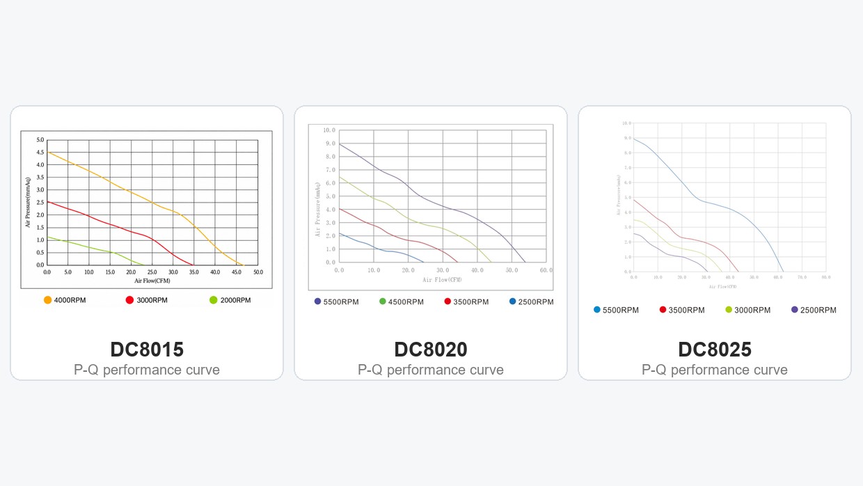
DC8015, DC8020 and DC8025 24V axial fan pressure–airflow (P-Q) curves
Before approving a fan for a filtered enclosure, engineers should establish three conditions:
The pressure drop across the clean filter at the target airflow.
The expected increase in resistance before the filter is cleaned or replaced.
The minimum airflow needed to maintain acceptable component temperatures under those conditions.
If a fan cannot meet the airflow requirement, increasing the filter area or improving the ventilation opening may be more effective than simply selecting a higher-speed model.
Account for Dust During Filter Maintenance
Filter design also affects contamination during servicing.
In dusty installations, particles collected on the filter or its housing may fall toward the fan opening when the filter is removed. Even stopping the fan before maintenance may not completely prevent this problem.
The enclosure design should therefore consider filter accessibility, removal direction, dust accumulation, and whether sensitive electronics remain exposed during replacement.
Maintenance intervals should be based on filter condition, pressure drop, environmental contamination, and equipment temperature rather than a universal replacement schedule.
Axial Fan vs. Blower for Restricted Cabinet Airflow
Axial fans move air primarily along their rotational axis and are commonly integrated into direct-through ventilation arrangements. Centrifugal blowers discharge air through a separate outlet direction and may suit installations requiring a concentrated or redirected airflow path.
Neither fan type is automatically better for every restrictive enclosure.
A high-static-pressure axial fan may perform adequately through a filter and short ventilation path. A centrifugal blower may be more suitable where the equipment requires a particular discharge direction or more complex ducting.
The decision should reflect the actual operating point and mechanical layout.
| Selection factor | Axial fan | Centrifugal blower |
|---|---|---|
| Straight-through cabinet ventilation | Often convenient to integrate | May require additional outlet space |
| Restricted airflow | High-pressure configurations may be suitable | Pressure-oriented designs may be suitable |
| Mechanical clearance | Thin and standard-depth frames available | Housing and discharge geometry must be checked |
| Enclosure contamination | Requires suitable filtration and sealing | Also requires suitable filtration and sealing |
In an existing control cabinet with a square ventilation opening, evaluating compatible axial fan configurations may be more practical than redesigning the enclosure for a blower.
However, when the required operating airflow cannot be achieved with a suitable axial fan, the airflow system or fan type should be reconsidered.
How Should OEMs Balance Cabinet Cooling Performance, Noise and Installation Space?
Once the airflow requirement and system resistance are known, engineers can compare specific fan configurations.
For control equipment with an 80mm mounting opening and a compatible 24V DC supply, YCCFAN offers several axial fan options with different depths and performance characteristics.
Rather than choosing a model solely by its maximum CFM, the important comparison is how the fan's size, pressure capability, electrical demand, and acoustic performance relate to the application. Browse YCCFAN DC cooling fan configurations to compare available 80mm options.
A Practical 24V Fan Comparison
| YCCFAN model | Dimensions | Maximum airflow | Maximum static pressure | Noise |
|---|---|---|---|---|
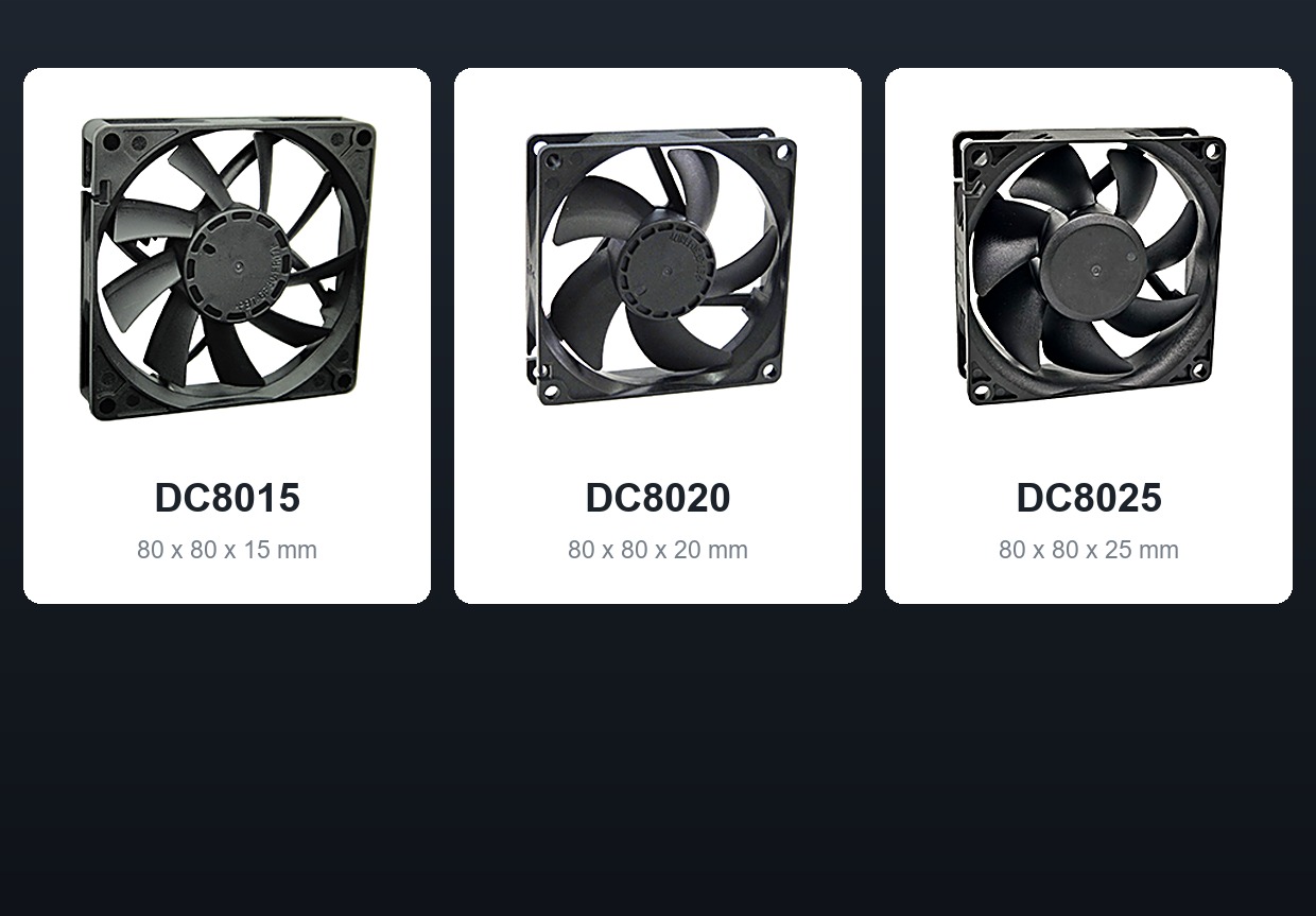
| DC8015 — YDH8015X24F | 80×80×15mm | 46.47 CFM | 4.55 mmH₂O | 36.30 dBA |
| DC8020 — YDD8020X24F | 80×80×20mm | 53.94 CFM | 8.95 mmH₂O | 46.61 dBA |
| DC8025 — YDD8025X24 | 80×80×25mm | 68.39 CFM | 10.78 mmH₂O | 47.74 dBA |
| DC8025 — YDH8025X24 | 80×80×25mm | 43.40 CFM | 4.80 mmH₂O | 35.05 dBA |
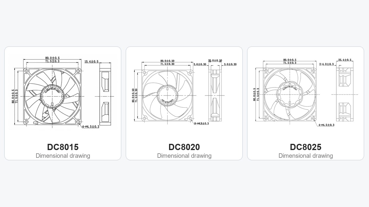
DC8015, DC8020 and DC8025 80mm axial fan depth comparison (15mm, 20mm, 25mm)
Values are based on published specifications for the listed 24V configurations. Maximum airflow and maximum static pressure occur under different test conditions. Actual operating airflow and acoustic comparisons require appropriate model-specific data and measurement conditions.
The comparison highlights three practical selection considerations.
Installation depth. A 15mm-deep configuration may be useful for compact assemblies where a 20mm or 25mm frame cannot fit. However, mechanical compatibility alone does not establish adequate cooling.
Filter resistance. A configuration with greater maximum static pressure may offer more suitable performance at elevated system resistance, but the exact airflow must be checked using the P-Q curve. The 20mm and 25mm configurations are therefore candidates for evaluation when the cabinet permits additional depth and the ventilation path is restrictive.
Noise limits. Higher cooling output is not always necessary. Within the 25mm frame family, the listed lower-speed configuration has a published noise rating of 35.05 dBA, compared with 47.74 dBA for the higher-output version. That difference can matter near an operator workstation, provided the quieter configuration still meets the thermal requirement.
These specifications illustrate how one mounting size can accommodate different design priorities. They should be used to narrow the selection, not replace equipment-level testing.
Where OEM equipment requires speed control or operating-status feedback, available PWM, FG, and RD configurations should also be confirmed for the exact fan model. A tachometer or rotation alarm cannot independently confirm that air is flowing through a partially blocked filter.
How Should OEM Engineers Validate a Cabinet Cooling Fan?
Catalog specifications are useful for identifying candidate fans, but the final decision should be based on the assembled equipment.
Validation should include representative heat loads, the actual filter and ventilation hardware, environmental conditions, and the operating states that matter to the application.
| Validation area | What to verify |
|---|---|
| Heat dissipation | Component power losses and critical temperatures |
| Electrical compatibility | Operating-voltage range, current and startup behavior |
| Filter resistance | Clean-filter and defined loaded-filter conditions |
| Airflow performance | Required airflow at the installed operating point |
| Acoustic performance | Noise under representative equipment conditions |
| Monitoring | Confirmed PWM, FG, RD or temperature-control functions, where applicable |
| Environmental protection | Complete ventilation assembly and required enclosure protection |
A fan that performs well on an open test bench may deliver less airflow after installation. Testing should therefore include the intended airflow path whenever practical.
For example, if a higher-pressure model is selected to address a restrictive filter, the engineering acceptance test should confirm that it actually maintains lower component temperatures at the expected filter resistance. If it does not, the limitation may lie in the filter, grille, exhaust opening, or internal cabinet layout rather than the fan alone.
Does a PLC Cabinet Fan Need UPS Power?
This question depends on which components remain energized during a power failure.
A cabinet may contain a VFD that stops when mains power is lost, while the PLC and communication modules continue operating from a UPS. The residual heat load during backup may therefore be much lower than during normal production.
If enclosure heat dissipation is sufficient for that reduced load, continuous fan operation during the backup period may not be necessary.
Where forced ventilation remains essential, the fan's running power and startup requirements must be included in the UPS design.
For reference, a 24V fan configuration with a published rated current of 0.10 A has a calculated nominal running input of approximately 2.4 W. That value is useful for preliminary power budgeting but does not establish startup demand or total UPS runtime.
The final decision should reflect the equipment's heat dissipation, backup duration, acceptable temperatures, and required operating state.
When Is a Cabinet Cooling Fan Unsuitable for Dusty Enclosures?
Filtered ventilation is not appropriate for every industrial environment.
If external air contains conductive dust, heavy oil mist, corrosive substances, or moisture that cannot be adequately controlled by the ventilation assembly, introducing ambient air may create unacceptable risks.
Ambient temperature is another limitation. A fan cannot actively cool the cabinet below the temperature of the incoming air.
Where external air is sufficiently cool but contamination must be excluded, a suitable closed-loop heat exchanger may be more appropriate. Where cooling below ambient is required, an appropriately rated active cooling system or another engineered solution may be necessary.
These conditions should be evaluated before selecting a standalone fan based on airflow or static pressure.
Cabinet Cooling Fan FAQs
Can a higher-CFM fan compensate for a clogged cabinet filter?
Not necessarily. A clogged filter increases airflow resistance, and maximum free-air CFM does not indicate the airflow available through the installed system. Filter maintenance, pressure-drop assessment, and the fan's P-Q curve are more useful for identifying the appropriate solution.
Can a 24V DC cooling fan be installed in an IP- or NEMA-rated control cabinet?
Yes, as part of a properly designed ventilation assembly. The complete installation must maintain the required protection, including the filter, housing, mounting, and seals. The standalone fan does not determine the enclosure rating.
Can fan-speed feedback identify a dirty cabinet air filter?
Not reliably by itself. FG generally provides rotational-speed feedback, while RD reports a defined rotation or fault condition. A fan can continue rotating normally while the filter restricts airflow. Differential pressure, airflow, temperature, or another appropriate method may be needed.
What should OEM engineers provide when requesting a cabinet cooling fan?
Useful information includes the cabinet dimensions, available fan depth, DC supply, component heat dissipation, ambient conditions, filter characteristics, expected system resistance, noise limits, and required control functions. These details help establish suitable fan configurations and sample acceptance conditions.
Conclusion
Choosing a cabinet cooling fan for a dusty industrial enclosure requires a system-level decision, not simply a comparison of catalog airflow ratings.
Engineers should first establish whether filtered ventilation is suitable, then calculate the required airflow and evaluate filter resistance, installation constraints, and thermal performance.
Different DC fan configurations can offer useful trade-offs between frame depth, static pressure, airflow, and noise. The appropriate selection depends on how those characteristics perform in the completed enclosure.
For OEM projects, providing the cabinet's heat load, ventilation arrangement, mounting dimensions, power supply, and operating conditions will support a more accurate fan selection and validation process.
Technical References
The following sources support the thermal management principles, airflow configurations, and environmental limitations discussed in this article. Product values are based on the linked YCCFAN specifications.
Pfannenberg — How to Select the Right Thermal Management Product
https://www.pfannenberg.com/en-gb/know-how/thermal-management/how-to-select-the-right-product/
Pfannenberg — Filterfan Configurations
https://info.pfannenbergusa.com/support/filter-fan-configurations
Chatsworth Products — How to Select a Filter Fan or Cooling Unit for Industrial Enclosures
https://www.chatsworth.com/en-us/resources/blogs/2018/how-to-select-a-filter-fan-or-cooling-unit-for-ind/