





DC Fan vs Blower Fan: How to Choose the Right Cooling Solution
Choosing between a DC axial fan and a DC blower fan is not simply a matter of selecting the option with the higher airflow or pressure value. The correct choice depends on how air must move through the equipment, how much resistance the airflow path creates, where the inlet and outlet can be positioned, and where the fan will operate on its pressure-airflow curve. A fan that performs well in open air may deliver much less useful airflow after filters, heat sinks, grilles, narrow passages, or ducts are added.
Quick answer: A DC axial fan is usually the better starting point when the system needs broad, straight-through airflow and has a relatively open flow path. A DC blower fan is usually more suitable when air must turn through a compact housing, enter a narrow duct, or continue moving against higher system resistance. These are selection tendencies, not universal rules. The final decision should be based on the required operating point and the performance curve of the specific model.
What Is the Difference Between a DC Fan and a Blower Fan?
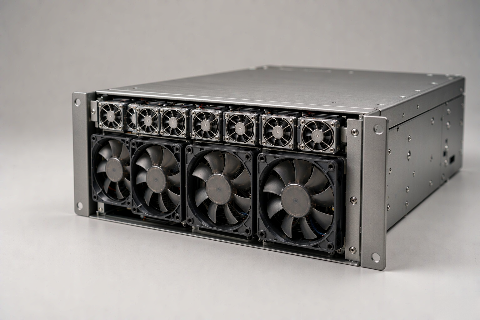
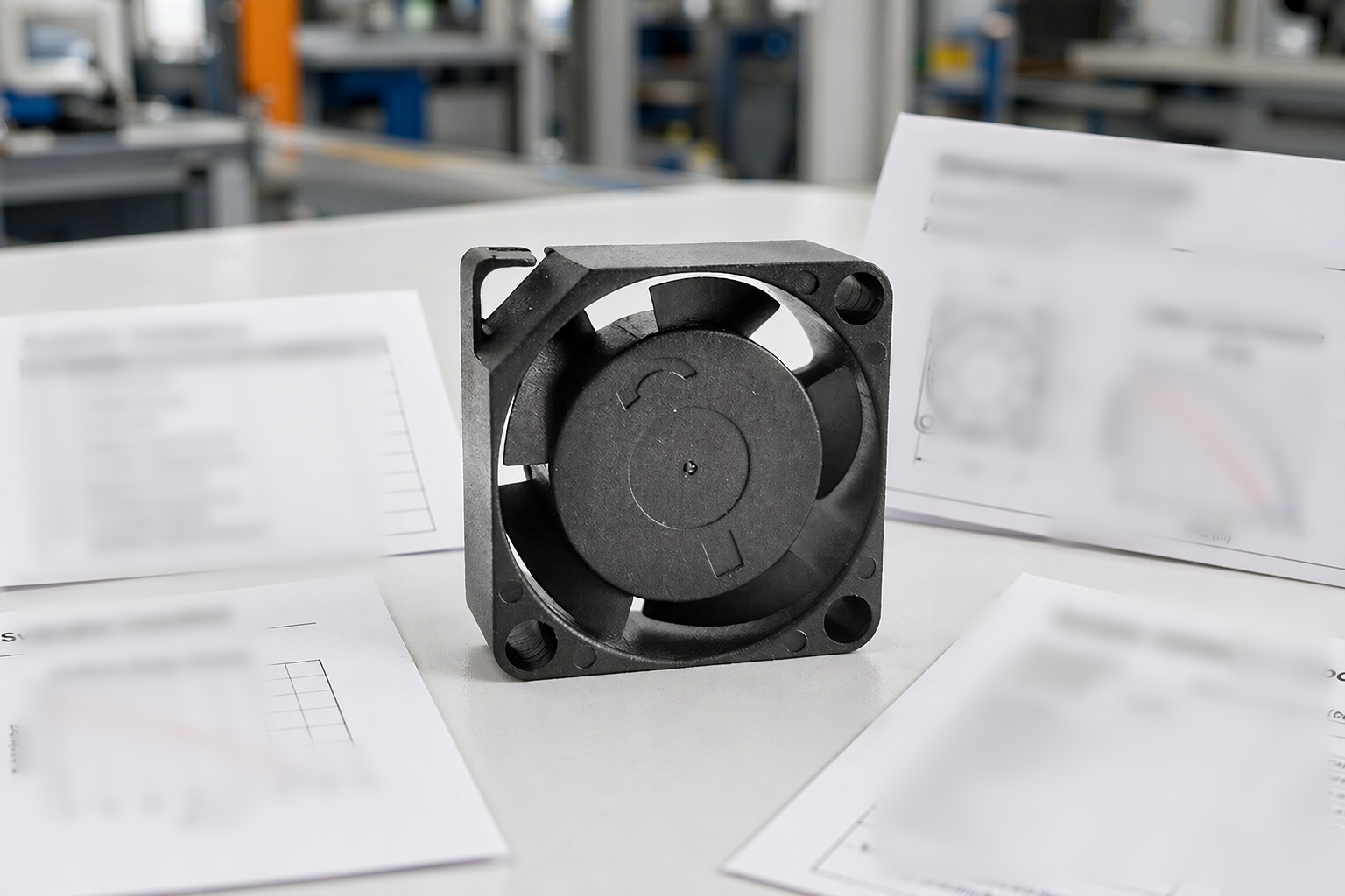
In compact electronic cooling, “DC fan” often refers to a DC axial fan. Its blades move air in a direction generally parallel to the motor shaft, so the air enters and leaves along a nearly straight path. This geometry supports efficient air exchange across a wide area and fits well on cabinet walls, vents, power supplies, and heat sinks when the downstream path is not highly restrictive.
A DC blower fan uses a centrifugal impeller. Air enters near the center of the impeller and leaves through an outlet that is typically positioned at roughly 90 degrees to the inlet. The housing collects and directs the discharge, creating a concentrated airflow path that can be connected more easily to a duct, nozzle, or targeted cooling channel.
Choose by Airflow Path and System Resistance
The most important difference is not the free-air CFM printed at the top of a datasheet. It is how the fan and the equipment behave together. Every grille, filter, heat sink, bend, duct, cable bundle, and reduced opening adds resistance. As airflow rises, this resistance normally increases, while the fan’s available pressure changes along its performance curve. The operating point is where the fan curve intersects the system resistance curve.
If the flow path is short and open, the operating point may remain close to the high-airflow region of an axial fan curve. If the path includes a dense filter, deep heat sink, multiple bends, or a small discharge opening, the system requires more pressure to maintain useful flow. In that situation, a centrifugal blower may be a stronger candidate. A high-static-pressure axial model can still be viable, so compare actual curves rather than selecting only by fan category.
When a DC Axial Fan Is Usually the Better Starting Point
Choose a DC axial fan first when air can enter and leave through large openings, the target is to exchange warm enclosure air with cooler ambient air, and components need broad rather than highly concentrated cooling. Typical examples include electronic cabinets, power supplies, control panels, telecom equipment, and general enclosure ventilation. The shallow frame can also simplify mounting when the available depth is limited but the front area is sufficient.
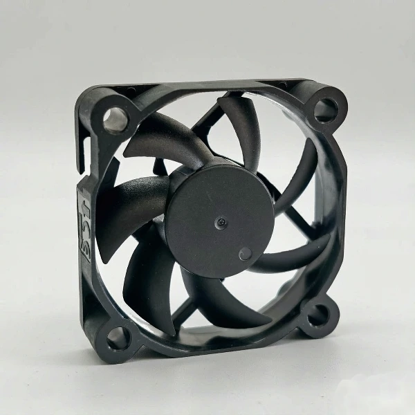
Axial airflow still needs a deliberate route. Intake and exhaust openings should be positioned to prevent recirculation, cables should not block the fan face, and the exit area should not be significantly smaller than the inlet without checking the resulting pressure loss. An axial fan installed behind a restrictive filter or grille can lose enough flow to make its free-air rating misleading.
When a DC Blower Fan Is Usually the Better Starting Point
Choose a DC blower fan first when the design needs a side outlet, a narrow air jet, or airflow through a ducted and resistant path. Blowers are commonly considered for compact projectors, 3D printers, medical or laboratory equipment, air purifiers, charging systems, and electronics with a localized heat source. Their outlet can aim air at a heat sink or through a channel that an open-frame axial fan cannot serve efficiently.
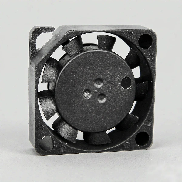
A blower does not automatically solve every high-resistance problem. Outlet geometry, inlet clearance, scroll design, rotational speed, and impeller dimensions all affect performance. A poorly integrated blower can create turbulence, tonal noise, or inlet starvation. The duct and outlet should therefore be designed around the selected blower rather than treated as an afterthought.
DC Fan vs Blower Fan Decision Matrix
| Selection factor | DC axial fan | DC blower fan |
|---|---|---|
| Air direction | Generally straight through, parallel to the shaft | Axial inlet with radial or side discharge |
| Typical system fit | Open vents, cabinet exchange, broad component cooling | Ducts, narrow channels, concentrated heat-source cooling |
| Pressure behavior | Often favored for larger flow at relatively low resistance | Often favored where more pressure rise is required |
| Installation profile | Thin frame and large open face | Compact housing with a defined outlet |
| Main selection check | Useful airflow at the actual system resistance | Useful airflow at the actual system resistance |
The same logic can be applied to concrete design conditions:
| Design condition | Preferred starting point | Why | What to verify |
|---|---|---|---|
| Large intake and exhaust openings | DC axial fan | Supports broad straight-through air exchange | Airflow at installed resistance and recirculation risk |
| Dense filter or restrictive heat sink | Compare high-pressure axial and blower models | The application needs sustained flow against pressure loss | Both fan curves at the estimated pressure drop |
| Narrow duct or nozzle | DC blower fan | Defined outlet is easier to connect to a channel | Outlet match, duct losses, and acoustic behavior |
| Very shallow mounting depth | DC axial fan | Thin frame can fit behind a panel or grille | Required face area and nearby obstructions |
| Limited face area but room for side discharge | DC blower fan | Compact inlet with directional outlet may fit better | Inlet clearance and housing orientation |
| Broad cooling across several components | DC axial fan | Wide airflow can cover a larger section | Component layout and dead zones |
| Targeted cooling of one hot component | DC blower fan | Concentrated discharge can feed a local channel | Jet position, heat-sink impedance, and vibration |
| Noise-sensitive equipment | No automatic winner | Noise depends on speed, operating point, turbulence, and structure | Sound data under comparable installed conditions |
Do Not Compare Airflow and Static Pressure Separately
Airflow and static pressure describe different parts of fan performance, but they must be read together. The maximum airflow value is normally measured near a low-resistance condition, while the maximum static pressure value occurs near a blocked-flow condition. Neither extreme represents normal cooling performance. The useful value is the airflow available at the pressure required by the system.
This is why two models with similar maximum airflow can behave differently after installation. One may retain more airflow as resistance rises, while the other may fall away quickly. Ask for a pressure-airflow curve and compare the candidate models at the same required pressure. For a step-by-step method, how to choose a DC fan based on airflow and static pressure explains the operating-point comparison in detail. If the equipment resistance is unknown, estimate it from component pressure-drop data or test a prototype with the intended grille, filter, heat sink, duct, and enclosure geometry installed.
Compare Space, Noise, Power, and Control Requirements
Thermal performance is the first filter, but the final choice also affects mechanical design and product behavior. An axial fan may require more open face area, while a blower needs room for its housing, inlet clearance, and side outlet. Changing from one format to the other late in development can force changes to ducts, brackets, PCB placement, and service access.
Noise should be evaluated at the intended operating point rather than by assuming one fan type is always quieter. Blade-passing tones, high rotational speed, turbulent inlet flow, restrictive grilles, vibration transfer, and duct resonance can dominate the result. A larger fan running more slowly may reduce noise in some open-flow systems, while a properly selected blower can avoid unstable flow in a restrictive channel. Compare acoustic specifications only when the test conditions are equivalent, then confirm performance in the finished equipment.
Power supply and control requirements also matter. Confirm rated voltage, current, startup behavior, allowable voltage range, speed control method, tachometer or alarm output, connector, lead length, and polarity protection. If the product changes cooling demand during operation, PWM speed control or a feedback signal may support a more balanced thermal and acoustic design than operating continuously at maximum speed.
How to Validate the Choice Before Production
Begin with the thermal load and the maximum acceptable component or exhaust-air temperature. Define where cooler air enters, where heated air leaves, and which restrictions sit between those points. Then estimate the required airflow and system pressure drop. This creates a target operating point that can be placed on candidate fan curves.
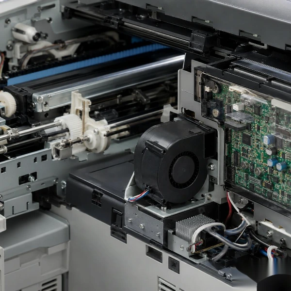
Prototype testing should reproduce the real airflow path. Use the intended enclosure panels, filters, guards, heat sinks, ducts, foam seals, and cable routing. Measure temperatures at critical components and monitor fan speed, current, airflow behavior, and noise across expected operating conditions. Testing only the fan on an open bench cannot reveal recirculation, leakage, inlet starvation, or resistance caused by the assembled product.
Leave a reasonable design margin for filter loading, component tolerance, altitude, ambient temperature, and aging, but avoid solving uncertainty by selecting the highest-speed model by default. Excess speed can increase noise and power consumption without fixing a poorly designed airflow path. Mechanical improvements such as enlarging vents, reducing sharp bends, sealing bypass leakage, or improving heat-sink access may produce a better result than adding fan power.
Common Selection Mistakes
The most common mistake is choosing by maximum CFM alone. Free-air airflow does not show how a fan performs after system resistance is added. Another mistake is treating maximum static pressure as the normal working condition; at or near that point, delivered airflow is very low. Engineers should compare the complete curve and identify the intended operating point instead of comparing isolated headline values.
It is also risky to assume that every blower provides more useful pressure than every axial fan. Fan size, speed, blade geometry, housing, and motor power can reverse a category-level assumption. The same caution applies to noise: comparing dBA values from different distances or test setups does not support a reliable decision. Use equivalent conditions and validate the installed system.
Information to Send a Cooling Fan Supplier
A useful selection request should describe the application rather than asking only for a fan with a certain voltage or frame size. Provide the available installation envelope, airflow direction, target airflow or thermal result, estimated static pressure or known restrictions, supply voltage, current limits, operating temperature, noise target, required life, bearing preference, connector and wire details, speed-control or feedback needs, environmental exposure, and expected order quantity. Drawings or photos of the airflow path can help identify obstructions and mounting limitations early.
If the pressure drop is not known, share the filter, heat sink, duct dimensions, vent openings, and internal layout. This allows the supplier to narrow the choice and recommend samples for system-level testing. YCCFAN offers separate ranges of DC axial fans and DC blower fans, so the product category can be selected after the airflow path and operating conditions have been defined rather than before.
Frequently Asked Questions
Is a blower fan always better for high static pressure?
No. Centrifugal blowers are commonly used when greater pressure rise and directional airflow are required, but the result depends on the specific fan curve, size, speed, housing, and system. Some high-static-pressure axial fans may outperform a small blower at a particular operating point. Compare both candidates at the same required pressure and validate them in the intended airflow path.
Which is better for an electronics enclosure, a DC fan or a blower fan?
A DC axial fan is often suitable for broad enclosure ventilation with large intake and exhaust openings. A blower is often more suitable when air must pass through a narrow channel, dense heat sink, or directed outlet. Enclosure size alone does not decide the answer; component placement, pressure loss, and the required airflow route are more important.
Can CFM alone determine the correct fan?
No. CFM without a corresponding static-pressure condition does not show how much air the fan will deliver in the assembled system. Review the pressure-airflow curve and identify the intersection with the system resistance curve. Maximum free-air CFM is useful for initial comparison, but it is not an installed performance guarantee.
Are blower fans noisier than axial fans?
Not in every case. Noise depends on fan size, rotational speed, blade design, operating point, inlet and outlet restrictions, vibration transfer, and measurement conditions. A blower can create tonal noise in a poorly designed duct, while an axial fan can become noisy near an unstable or highly restricted operating condition. Compare data under equivalent conditions and test the final assembly.
Can an axial fan be connected to a duct?
Yes, but the duct resistance and transition geometry must match the fan’s pressure capability. Long ducts, small cross-sections, abrupt bends, and restrictive outlets can reduce airflow significantly. If the required operating point falls outside the efficient range of the axial fan, a blower or a different high-pressure fan design may be more appropriate.
What specifications should I compare before requesting samples?
Compare the pressure-airflow curve, voltage, current, power, speed, noise test conditions, dimensions, mounting, outlet direction, bearing system, expected life conditions, operating temperature, control signals, feedback outputs, connector, and environmental protection. The sample should then be tested inside the intended enclosure with all major airflow restrictions installed.
Select the Fan Around the Real Cooling Path
The practical choice in a DC fan vs blower fan comparison is determined by the airflow route and the required operating point. Start with an axial fan for broad, straight-through cooling in a relatively open system. Start with a blower when air must be concentrated, redirected, or moved through greater resistance. Then verify the decision with comparable curves and an assembled prototype.
Need help narrowing the options? Review YCCFAN’s DC fan range for straight-through enclosure cooling or the DC blower fan range for directional and higher-resistance airflow paths. Send your available space, voltage, airflow route, restrictions, control requirements, and target quantity to discuss suitable models and samples.
Compare DC axial fan products and blower alternatives before fixing the airflow path in your design.