







2-Wire vs 3-Wire vs 4-Wire DC Fans: Power, Speed Signal, and PWM Explained
A 2-wire, 3-wire, and 4-wire DC fan may look almost identical from the frame side, yet the extra conductors change what the host system can observe and control. The short answer is simple: a 2-wire fan has power and ground, a 3-wire fan adds a speed-feedback output, and a 4-wire fan adds a dedicated PWM speed-control input. The connector shape and wire colors are useful clues, but the fan datasheet and pinout—not color alone—must be the final authority.
2-Wire vs 3-Wire vs 4-Wire DC Fans at a Glance
| Fan type | Typical conductors | Speed feedback | Dedicated speed command | Best fit |
|---|---|---|---|---|
| 2-wire | Power, ground | No | No | Simple fixed-speed cooling |
| 3-wire | Power, ground, tach/FG | Yes | Usually no | Fault monitoring and RPM measurement |
| 4-wire | Power, ground, tach/FG, PWM | Yes | Yes | Closed-loop thermal control |
The terms “tach,” “speed sense,” and “FG” commonly describe the pulse output used to estimate rotational speed. “PWM” describes a separate logic input on a four-wire fan. These functions should not be confused with switching the fan’s power lead on and off.
How a 2-Wire DC Fan Is Connected
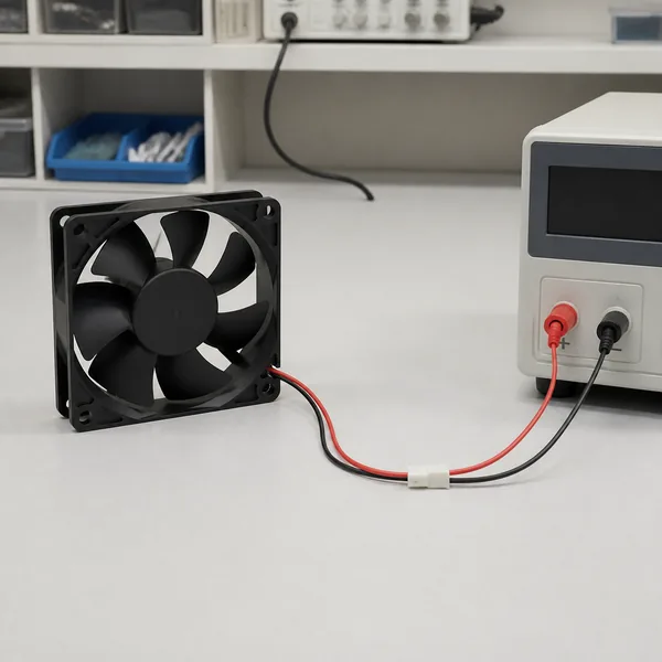
A 2-wire fan is the simplest arrangement. One conductor supplies the rated DC voltage and the other is the return or ground. In many products red is positive and black is ground, but industrial cable colors can differ. Confirm the label or manufacturer drawing before applying power.
When the rated voltage is applied, the internal brushless motor driver starts and commutates the motor. The host receives no direct indication of RPM or rotor status. A two-wire fan is therefore a practical choice when the system only needs dependable airflow whenever power is present and does not need fan telemetry.
Speed reduction by lowering the supply voltage may be possible only within the model’s specified operating-voltage range. If the voltage falls below the start threshold, a stationary fan may fail to restart even though a running fan appeared stable at that voltage. Power-side PWM can also create audible or electrical problems unless the fan is explicitly designed for that method.
What the Third Wire Does on a DC Fan
A 3-wire DC fan retains the same power and ground leads and adds a speed-signal output. This third conductor does not normally power the fan and is not automatically a speed-control input. It reports rotation to a motherboard, PLC, embedded controller, or alarm circuit.
The output is commonly an open-collector or open-drain pulse signal, so the receiving circuit may need a pull-up resistor to an approved logic voltage. Many fans produce two pulses per revolution, but that ratio is model-dependent. If a fan produces two pulses per revolution, RPM can be calculated as pulse frequency multiplied by 60 and divided by two. The product specification must confirm both the output circuit and pulse ratio.
Because the motor still receives power through the first two wires, a three-wire fan can provide failure detection even when the host does not control speed. Some systems vary the supply voltage to control a 3-wire fan, but the changing supply can affect the quality or availability of the tach signal. Verify the controller and fan together at minimum speed, startup, and fault conditions.
Why a 4-Wire Fan Has a Separate PWM Lead
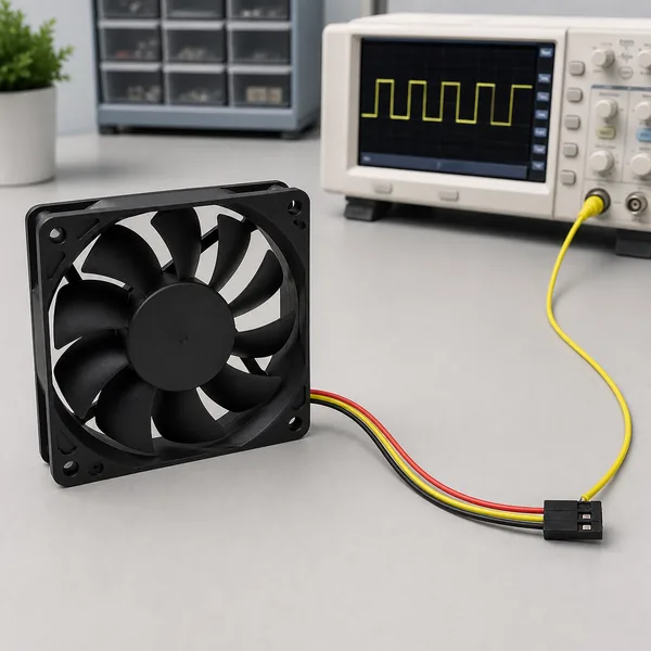
A 4-wire fan adds a dedicated control input while keeping power continuously available to the internal motor electronics. The host changes the PWM duty cycle on the control lead, and the fan’s internal driver interprets that command to adjust speed. The tachometer lead remains available for RPM feedback.
This separation is the main engineering advantage of four-wire control. The fan electronics stay powered, the speed command travels on a low-current signal lead, and the controller can compare requested cooling with measured fan response. It is well suited to servers, power electronics, communications equipment, and other systems where thermal load changes over time.
The electrical approach is documented in the Intel 4-Wire PWM Controlled Fans specification. Manufacturer implementations still vary; for example, Delta publishes model-specific PWM frequency, duty-cycle, and FG limits in its PWM fan technical information.
Do not assume that every 4-wire fan follows the same electrical levels, PWM frequency, minimum duty behavior, or fail-safe response. The widely used Intel four-wire specification describes a 25 kHz target and an open-collector/open-drain style control interface for compatible PC fans. Industrial fans may specify different ranges. Some run at maximum speed when the PWM lead is disconnected; others use a minimum-speed or stop behavior. Always follow the exact datasheet.
DC Fan Wire Colors Are Clues, Not a Standard
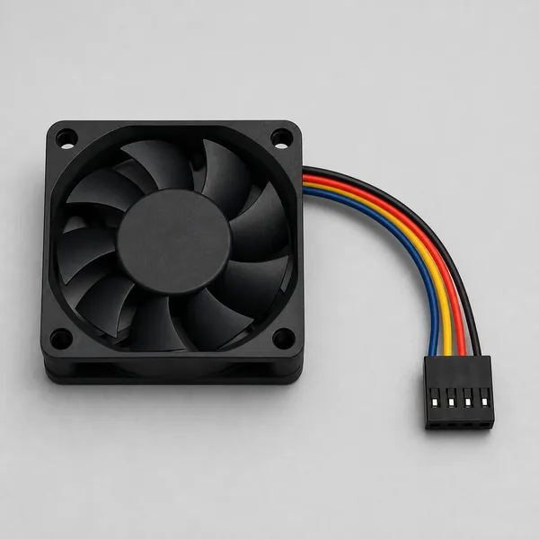
Red for positive and black for ground are common conventions. Yellow, white, blue, and green are often used for tachometer, alarm, or PWM functions, but their meaning changes between manufacturers and product families. Two fans with the same colors may not share the same pin order.
Before connecting a replacement fan, record the original connector orientation and compare the pin numbers, rated voltage, current, signal type, and control logic. Never identify a pin only by its position in a loose connector: drawings may show the mating face while you are looking at the wire-entry side, which reverses the apparent order.
Are 3-Wire and 4-Wire Fans Compatible?
Mechanical fit does not prove electrical compatibility. In the common PC-style arrangement, a keyed 3-pin fan can often operate from a compatible 4-pin header, but it normally loses dedicated PWM control and may run at full speed or use voltage control if the host supports it. A compatible 4-pin fan can often run from a 3-pin header because power, ground, and tach occupy corresponding positions, but its PWM lead is unused and the fan may default to full speed.
Those assumptions should not be carried into industrial equipment without checking documentation. Connector pitch, locking features, voltage, current capacity, polarity, signal voltage, and pin order can all differ. A controller header must also be able to supply the fan’s startup current; a matching plug does not guarantee an adequate power stage.
How to Choose the Right Fan Wiring
Choose 2-wire when the cooling requirement is fixed and the host only switches the fan on or off. Choose 3-wire when the system must detect a stalled or failed fan or log RPM but does not need a separate speed command. Choose 4-wire when the system needs efficient speed control across changing thermal loads while retaining speed feedback.
Electrical interface is only one selection dimension. Airflow, static pressure, noise, size, bearing system, life, operating temperature, ingress conditions, and connector retention still determine whether the fan is appropriate. YCCFAN’s DC fan product range provides a starting point for matching mechanical and airflow requirements before confirming optional FG, RD, alarm, or PWM functions for a particular model.
For a replacement or custom harness, send the fan model, rated voltage, connector drawing, pin sequence, cable length, required feedback, and controller interface to the supplier. YCCFAN states that it offers OEM and ODM customization; the cooling fan engineering contact can confirm which signal options and wire assignments are available rather than relying on a generic color chart.
A Safe Wiring and Commissioning Checklist
- Confirm rated voltage, polarity, and maximum current from the fan label and datasheet.
- Identify pin numbers from the correct connector viewing direction.
- Verify whether the third lead is FG, tachometer, rotation-detect, or alarm.
- Confirm the signal output type, pull-up voltage, current limit, and pulses per revolution.
- For four-wire control, verify PWM voltage levels, frequency range, duty-cycle behavior, and the response to an open control lead.
- Check that the header and wiring can withstand startup and locked-rotor current.
- Test startup at minimum command, full-speed operation, tach reading, stop behavior, and fault response before final installation.
Frequently Asked Questions
Can the third wire on a fan control speed?
Usually no. On a typical 3-wire brushless DC fan, the third wire is a tachometer or FG output. Speed control, if supported, is normally achieved by varying supply voltage or by using a separate PWM input on a 4-wire model.
Will a 4-wire fan run if the PWM wire is disconnected?
Many compatible four-wire fans default to full speed when the PWM input is open, but this behavior is not universal. Check the model’s control specification before designing a fail-safe strategy.
Can I connect a 12 V fan directly to a microcontroller pin?
No. A microcontroller I/O pin should not power the fan motor. Use a correctly rated power supply and driver or controller circuit, share ground only where the interface requires it, and respect the tach and PWM electrical limits.
Why does the fan report zero RPM even though it is spinning?
Common causes include a missing pull-up resistor, an incompatible logic voltage, incorrect pin identification, an unsupported pulse-count assumption, or a tach signal that becomes unreliable under power-side speed control.
Conclusion
The wire count describes the interface, not the fan’s cooling capacity. Two wires provide power, three wires add rotational feedback, and four wires add a dedicated speed-control channel. Treat colors as hints, verify the exact pinout and signal specification, and test the complete fan-controller combination under startup, low-speed, full-load, and fault conditions.
Compare DC fan models by voltage range, tach output and PWM support before finalizing the wiring design.