





Server Rack Cooling: How Much Airflow Does a Rack Need?
A server rack typically needs about 160–200 CFM of airflow for each kilowatt of air-cooled IT load when the allowable inlet-to-outlet temperature rise is approximately 9–11°C. For a more accurate estimate, use:
CFM = 1.76 × Air-Cooled Heat Load (W) ÷ Allowable Temperature Rise (°C)
For example, a 3 kW air-cooled server rack with a 10°C temperature rise requires approximately 528 CFM. This is the theoretical airflow needed to remove the heat—not the total free-air CFM that should simply be added from fan datasheets.
The final server rack cooling requirement must also account for equipment airflow, rack-door resistance, filters, cable obstructions, bypass air, hot-air recirculation and the fan’s actual operating point. For a liquid-cooled rack, calculate only the heat that remains in the air path. If the equipment manufacturer provides airflow or inlet-temperature requirements, use those values to verify the calculation.
Server Rack Airflow Calculator: Calculate CFM from Heat Load
A practical server rack cooling calculator starts with two values: the heat released into the air and the allowable temperature rise across the equipment.
Use either of the following formulas:
CFM = 1.76 × Air-Cooled Heat Load (W) ÷ ΔT (°C)
CFM = 3.16 × Air-Cooled Heat Load (W) ÷ ΔT (°F)
For metric airflow:
m³/h = 3.0 × Air-Cooled Heat Load (W) ÷ ΔT (°C)
The heat-load value should represent the portion of electrical power ultimately released into the rack air. In a conventional air-cooled server rack, most electrical power consumed by the IT equipment becomes heat. In a liquid-cooled system, some heat may be removed by the liquid loop, so only the remaining air-cooled load should be entered into the formula.
The allowable temperature rise, or ΔT, is the difference between the air entering and leaving the equipment. Selecting a smaller ΔT increases the required airflow. Allowing a larger ΔT reduces the calculated airflow but may increase exhaust-air and component temperatures.
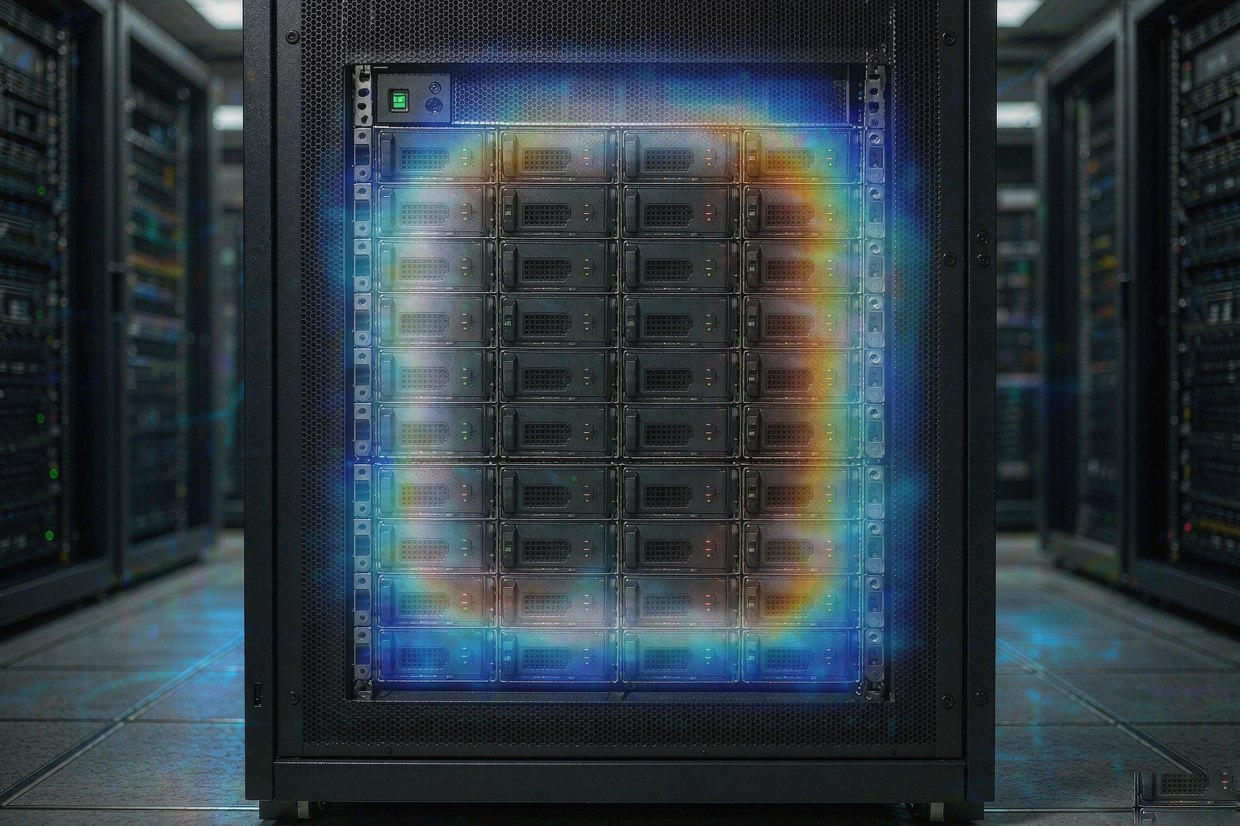
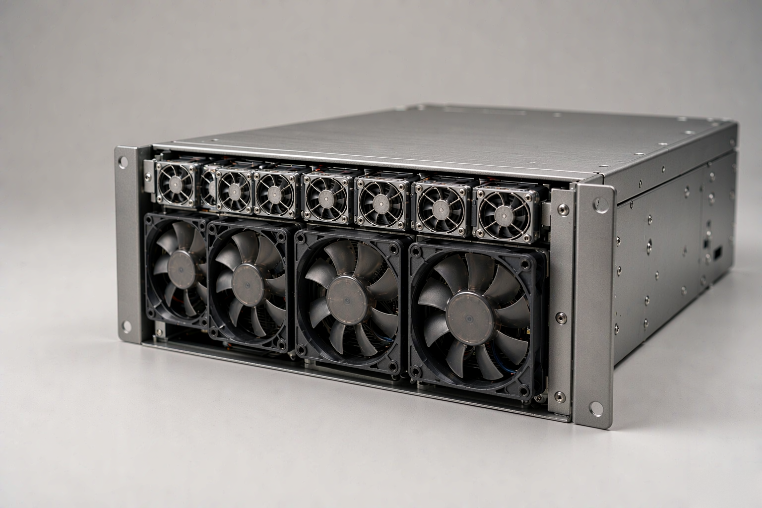
Front-to-rear server rack airflow: cool air enters through the perforated front door and warm exhaust leaves at the rear.
Server Rack Cooling Calculation Example
Assume that a server rack has a 3 kW air-cooled load and an allowable temperature rise of 10°C:
CFM = 1.76 × 3,000 ÷ 10 = 528 CFM
The initial airflow requirement is therefore approximately 528 CFM.
If the project has a known reason to apply a 15% design allowance—for example, expected filter loading or measurement uncertainty—the adjusted value would be:
528 × 1.15 = 607 CFM
This allowance is only an example. There is no universal percentage that should automatically be added to every server rack cooling system. The appropriate margin depends on system resistance, equipment tolerances, redundancy requirements, environmental conditions and the consequences of insufficient cooling.
CFM per kW for Server Rack Cooling
The following table provides a preliminary reference for converting air-cooled IT load into rack airflow:
| Air-cooled IT load | ΔT 5°C | ΔT 10°C | ΔT 15°C |
|---|---|---|---|
| 1 kW | 352 CFM | 176 CFM | 117 CFM |
| 3 kW | 1,056 CFM | 528 CFM | 352 CFM |
| 5 kW | 1,760 CFM | 880 CFM | 587 CFM |
| 10 kW | 3,520 CFM | 1,760 CFM | 1,173 CFM |
A commonly quoted range of 160–200 CFM per kW corresponds approximately to an 8.8–11°C temperature rise. It can be useful for an early estimate, but it should not be treated as a universal server fan CFM requirement.
Different servers can use different fan-control logic, internal pressure paths and allowable inlet temperatures. Two racks with the same electrical load may therefore require different airflow. Manufacturer-supplied equipment airflow and thermal limits should be compared with the calculated value whenever they are available.
For mixed or liquid-cooled racks, first estimate the heat that remains in the air. For example, if a 10 kW rack transfers 70% of its heat to a liquid loop, the airflow calculation should begin with the remaining 3 kW air-cooled load rather than the full 10 kW electrical load.
Why Calculated CFM Is Not Actual Rack Airflow
The calculation above estimates how much air is required to carry away the heat. It does not confirm that the selected fans can deliver that airflow through the installed rack.
Fan datasheets normally show maximum airflow under free-air or very low-resistance conditions. After installation, rack doors, filters, grilles, heat sinks, cable bundles, equipment passages and outlet restrictions create static pressure. As resistance increases, the airflow delivered by a fan decreases.
The actual airflow is determined by the point where the fan’s pressure–airflow curve intersects the resistance curve of the complete system. This intersection is the fan’s operating point. A fan rated for 20 CFM in free air may deliver substantially less after it is installed behind a filter or inside a restricted rack.
This also means that ten fans rated for 20 CFM do not necessarily provide 200 CFM through the equipment. Parallel-fan interaction, uneven pressure, leakage and restricted inlet or outlet areas can all reduce useful airflow. The number of server rack cooling fans should therefore not be calculated by simply dividing the rack requirement by the maximum CFM of one fan.
A more reliable process is to calculate the required delivered airflow, estimate pressure loss at that airflow and compare the resulting duty point with the P-Q curve of the exact fan model. The complete fan tray or rack should then be tested under representative conditions.
For a detailed explanation of this process, see YCCFAN’s guide to reading a fan P-Q curve and finding the real operating point.
Rack Airflow Management and Cooling Validation
Effective rack airflow management ensures that cooling air reaches the equipment inlets, passes through the heat-producing components and leaves the rack without returning to the intake side.
Most rack-mounted servers use front-to-rear airflow. Equipment should therefore be installed in a consistent direction, with sufficient clearance at both the front intake and rear exhaust. An added fan tray should support the server airflow direction rather than oppose the equipment’s internal fans.
Empty rack spaces should be closed with blanking panels. Unsealed cable openings, gaps beside equipment and unused rack positions can allow cold air to bypass the servers or permit hot exhaust air to return to the front. A rack may appear to have enough total airflow while some equipment inlets still receive insufficient cool air.
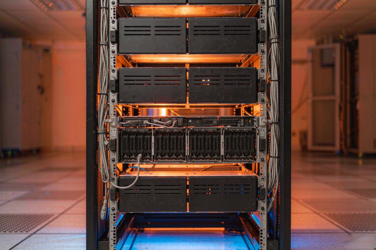
Rack airflow management: blanking panels seal empty spaces and cable bundles are routed clear of the air path.
Door construction also matters. A restrictive front or rear door creates pressure loss, particularly when filters, decorative panels or dense perforations are used. Before increasing fan capacity, check whether the airflow path can be improved by opening blocked areas, sealing bypass paths or reorganizing cables.
After the initial rack cooling design is complete, validate it with the actual equipment, doors, panels, filters and cables installed.
A single room-temperature sensor is not enough to confirm that cooling a server rack is effective. The most important temperatures are those measured at the actual equipment air inlets. If the upper part of the rack is significantly warmer, hot-air recirculation, bypass airflow or uneven pressure may be present.
Testing should also consider the project’s likely operating extremes. These may include higher IT load, the maximum expected room temperature, partially loaded filters or reduced fan availability. The rack cooling solution is acceptable only when equipment inlet conditions remain within the limits specified by the equipment manufacturer.
| Validation item | What to verify |
|---|---|
| Rack inlet temperature | Measure at the lower, middle and upper sections |
| Exhaust temperature | Compare it with the assumed design temperature rise |
| Equipment airflow direction | Confirm consistent front-to-rear movement |
| Rack openings | Check blanking panels, cable openings and air leakage |
| Fan operating condition | Test at the intended voltage, speed and control signal |
| Loaded condition | Verify performance at representative IT load |
| Degraded condition | Check filter loading or one-fan-out operation where required |
From Required Airflow to Server Rack Cooling Fan Selection
Once the required airflow and estimated static pressure are known, a suitable fan can be evaluated at the target operating point. Fan size, voltage, speed, pressure capability, noise, control functions and available installation space should all be considered.
YCCFAN’s DC4020F 40 × 40 × 20 mm DC cooling fan provides a useful component-level example. Depending on the exact configuration, the series supports 5 V, 12 V and 24 V operation, with published maximum performance up to 13.76 CFM and 13.89 mmH₂O static pressure.
These figures are maximum product values under the stated test conditions. They do not mean that one DC4020F will automatically deliver 13.76 CFM after installation in every rack.
The model may be evaluated for a compact fan tray, local equipment zone or another restricted installation when its dimensions, voltage and P-Q curve match the required duty point. The final quantity and arrangement depend on system resistance, fan interaction, mounting, control strategy and the airflow already provided by the servers’ internal fans.

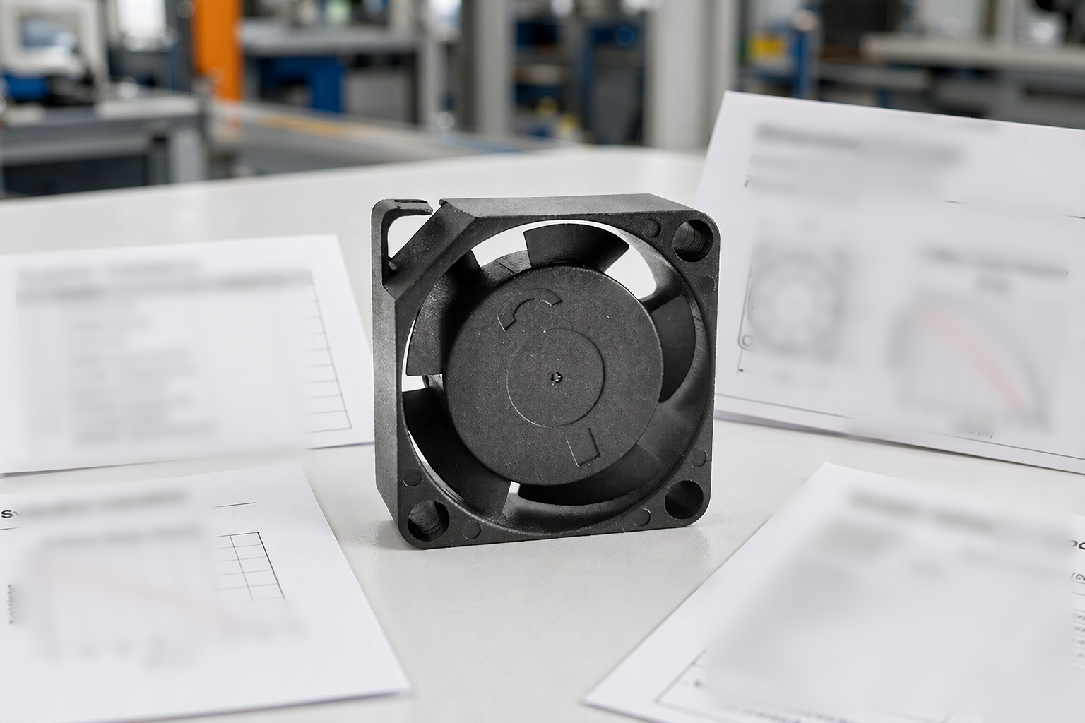
A DC4020F 40 × 40 × 20 mm DC cooling fan evaluated for a compact fan tray inside a rack.
The same evaluation method applies to larger server rack fans:
Calculate the required airflow → estimate system resistance → compare the P-Q curve → test the assembled rack.
Additional fans can help when the rack has a defined airflow path that needs more pressure or delivered airflow. They are unlikely to solve overheating caused by blocked server inlets, failed internal fans, reversed equipment orientation, severe hot-air recirculation or insufficient room-level cooling.
A suitable commercial next step is therefore not simply to request “a fan with more CFM.” The supplier should receive the required delivered airflow, estimated static pressure, installation space, voltage, noise limit, control requirements and expected operating environment. This information allows a fan or fan-tray configuration to be assessed against the real application.
Frequently Asked Questions About Server Rack Cooling
Is 160–200 CFM per kW enough for server rack cooling?
It can be a reasonable preliminary range when the allowable temperature rise is approximately 9–11°C. It should still be checked against the equipment manufacturer’s airflow, power and inlet-temperature requirements.
Should rack airflow be calculated from maximum or typical power?
Maximum power provides a conservative upper-bound check, while typical power may better represent normal operation. A practical design compares both and confirms that the cooling system can respond safely when the IT load increases.
Does a liquid-cooled server rack still need airflow?
Usually yes. Power supplies, memory, storage, networking components and other parts may continue to release heat into the air. Use the remaining air-cooled heat load in the airflow calculation instead of assuming that the entire rack requires no ventilation.
Can rack cooling fans replace internal server fans?
No. Rack fans manage airflow around the equipment and through the cabinet. Internal server fans move air through the chassis, heat sinks and components. External airflow cannot reliably compensate for a failed or obstructed internal cooling system.
How does altitude affect server rack cooling?
Higher altitude reduces air density, so a given volumetric airflow carries less heat. Installations that differ significantly from the fan or equipment test conditions may require air-density correction, manufacturer guidance and on-site validation.
Conclusion
Server rack cooling should begin with the air-cooled heat load and the allowable inlet-to-outlet temperature rise. A typical preliminary range is 160–200 CFM per kW, while the heat-balance formula provides a more transparent estimate for a defined ΔT.
The calculation is only the first step. Actual rack airflow also depends on equipment behavior, pressure loss, rack airflow management and the operating point of the selected fans. Calculate the required delivered airflow, compare it with the exact fan P-Q curve and validate the complete rack under representative load.
This approach provides a more reliable server rack cooling solution than selecting fans from maximum CFM alone. For component-level options, review YCCFAN’s DC cooling fan range or contact the engineering team for a duty-point assessment.