





How to Select Server Fans for 1U, 2U, and 4U Systems
Selecting a server fan starts with measuring the usable opening and installation depth, then matching the fan’s P-Q curve to the resistance of the completed chassis.
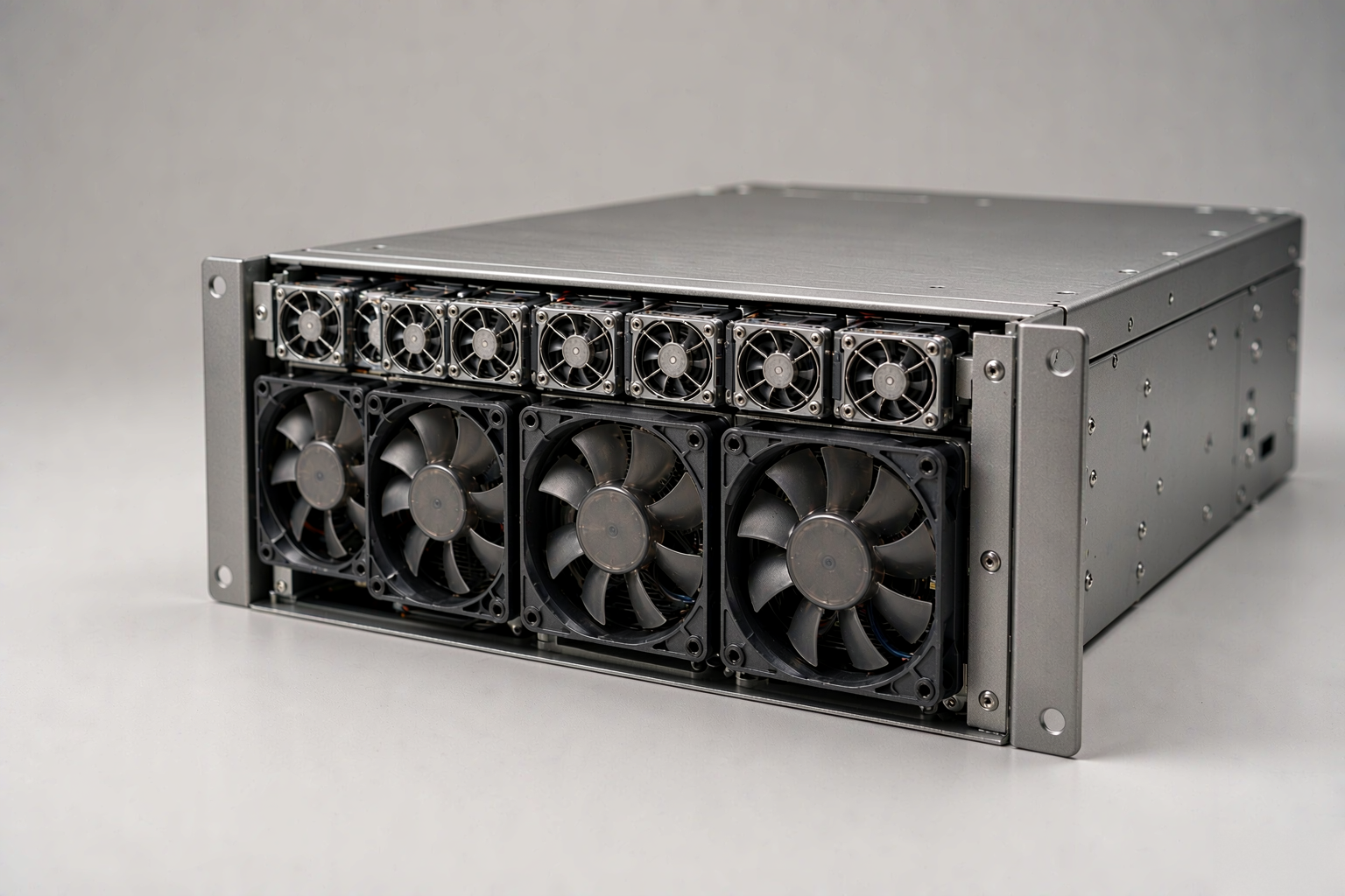
Rack height provides only a starting point. A 1U server commonly uses 40mm fans, a 2U system may accommodate 60mm or 80mm fans, and a 4U system may support 80mm, 92mm, or 120mm fans. The correct choice also depends on heat sinks, drive backplanes, air ducts, guards, power limits, and fan-control requirements.
A larger fan is not automatically better, and a fan with higher free-air CFM may not deliver more airflow after installation. Effective selection requires the correct dimensions, adequate static pressure, electrical compatibility, and testing in the closed chassis.
How Server Fan Size Changes Between 1U, 2U, and 4U
One rack unit is 44.45mm high, but the full external height is not available for a fan. Sheet metal, rails, brackets, vibration clearance, and service space all reduce the usable opening.
The server form factor therefore suggests a starting range rather than a final fan size.
| System | Practical starting point | Factors that can change the selection |
|---|---|---|
| 1U | Usually 36–40mm, with 40mm being common | High airflow resistance, available depth, fan-wall design, and passive heat sinks |
| 1.5U–2U | Often 60–80mm when the internal opening permits | Drive backplanes, redundant modules, cable space, and mounting geometry |
| 3U–4U | Often 80–120mm, depending on the panel and fan wall | GPU or storage density, airflow dead zones, pressure requirements, and controller design |
These ranges are not fixed rules. Two 2U systems, for example, may require different fans because their internal layouts and airflow resistance are different.
How to Measure Server Fan Size and Depth
Measure the actual internal space before selecting a server fan. The required dimensions include the usable fan opening, maximum frame depth, mounting-hole spacing, inlet and outlet clearance, guard or grille thickness, connector position, and cable route. The measurement should also account for nearby circuit boards, drive cages, heat sinks, and other structures that could obstruct installation or airflow.
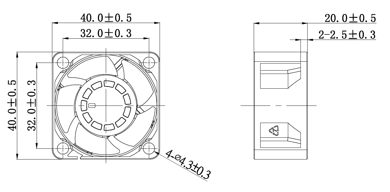
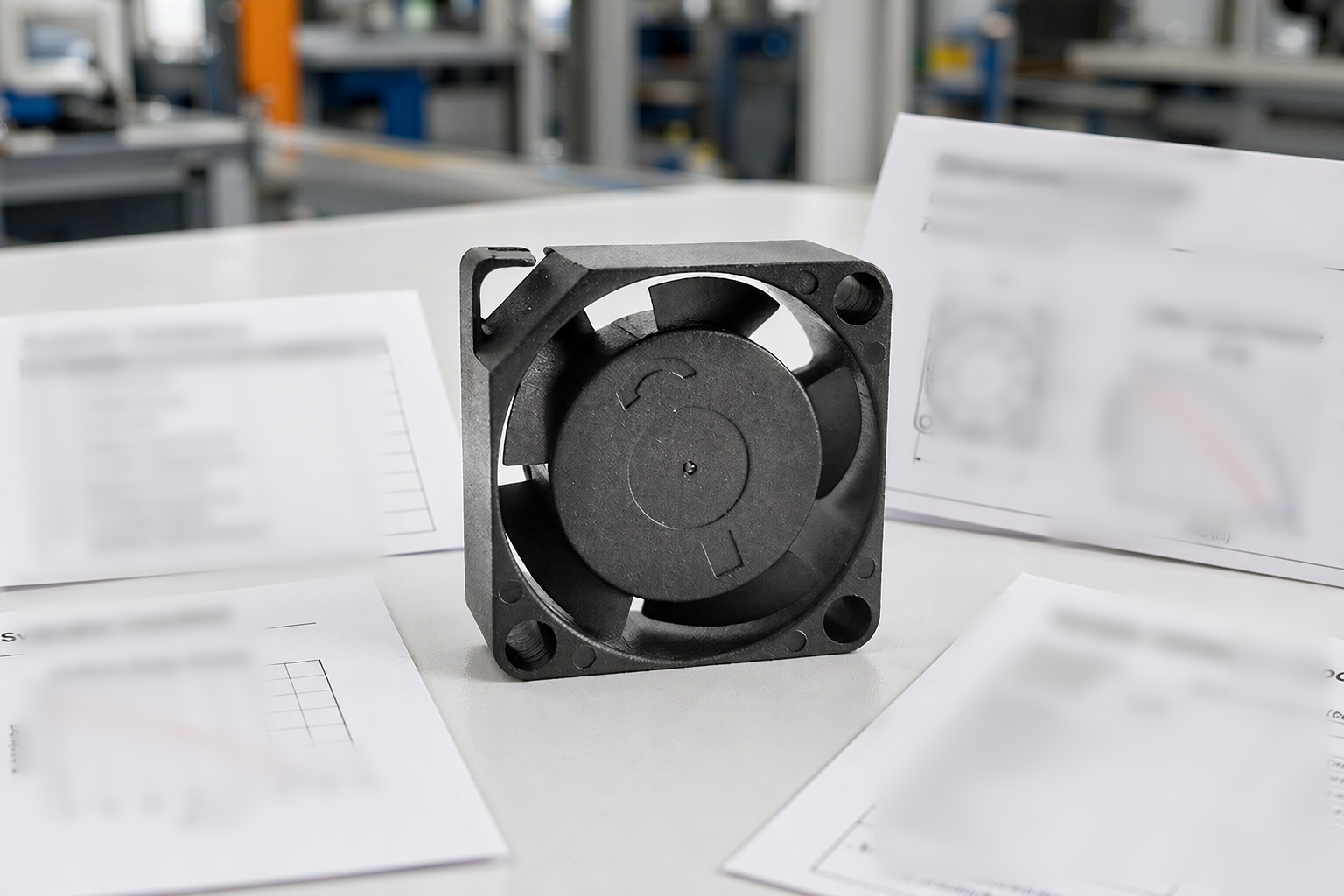
YCCFAN DC4020F outline drawing (40 × 40 × 20mm): frame size, depth, and mounting-hole spacing must be measured inside the chassis.
Fan depth affects both fit and performance. Fans with the same face size but different depths, such as 20mm, 28mm, or 38mm, may use different impellers, motors, and frame designs. Their airflow and static-pressure capabilities can therefore be significantly different.
The airflow path should be inspected at the same time. Check whether the fan must draw or push air through a grille, filter, drive cage, backplane, or heat sink. Confirm the airflow direction and make sure that nearby structures do not block part of the inlet or create an abrupt restriction at the outlet.
Do not use the nominal 1U, 2U, or 4U height as the available fan diameter. Always measure the usable space inside the chassis.
How to Select a Small Server Fan for a 1U System
A small server fan in a 1U chassis must often move air through densely packed components using a limited inlet area. Static pressure and frame depth are therefore especially important.
A thin fan may be suitable for a short and relatively open airflow path. If the air must pass through a dense heat sink, drive wall, or accelerator duct, a deeper fan with stronger pressure performance may be necessary.
For example, the YCCFAN DC4020F uses a 40 × 40 × 20mm frame and may be considered where installation depth is limited.
When 28mm of depth is available and the airflow path has greater resistance, the YCCFAN DC4028F provides a deeper 40mm option for comparison.
The two fans should not be compared only by maximum airflow or maximum static pressure. The more relevant value is the airflow each fan can maintain at the expected system pressure.
If a single-rotor fan cannot reach the required operating point, a tandem or counter-rotating design may be considered. These configurations can improve pressure capability, but they also affect installation depth, power consumption, noise, control requirements, and failure behavior. The complete assembly must be evaluated rather than treating it as a standard single fan.
Why Quiet Server Fan Replacements Can Fail in 1U Systems
Replacing a loud 1U fan with a quieter fan of the same nominal size can increase component temperatures.
The common mistake is comparing frame size, free-air CFM, or advertised sound level while overlooking the pressure capability of the original fan. In a restrictive 1U airflow path, a low-pressure replacement may move considerably less air through the drive backplane and passive CPU heat sinks, even if it appears to operate normally.
Before replacing a server fan, compare the complete P-Q curves rather than relying on frame size or free-air CFM. Confirm the airflow available at the expected system pressure, as well as the startup and full-speed current, PWM response, tachometer or FG output, alarm behavior, minimum speed requirement, connector, and pin configuration.
The server BMC may expect a specific speed range or feedback signal. An incompatible fan can trigger a fault, cause other fans to accelerate, or prevent the cooling system from responding correctly.
After replacement, test CPU, memory, storage, and other critical component temperatures with the chassis cover installed and under a representative workload. An open-cover test does not reproduce the normal airflow resistance of the server.
How to Select a Server Cooling Fan for a 2U System
A 2U chassis may accommodate a 60mm or 80mm server cooling fan, but diameter alone does not determine which one will perform better.
A deep 60mm fan can be useful when brackets, cables, or redundant modules restrict the available opening and the airflow path requires more pressure. An 80mm fan has a larger swept area and may move air more efficiently in a less restrictive path, provided the mounting structure and fan wall distribute that airflow across all critical components.
The YCCFAN DC6038 uses a 60 × 60 × 38mm frame. It can be evaluated in layouts that need a compact face size combined with a deeper frame.
The YCCFAN DC8025 uses an 80 × 80 × 25mm frame. It may suit a chassis with a larger opening but more limited installation depth.
An 80mm fan should not be selected simply because it is larger. A deep 60mm fan may maintain more airflow through a restrictive drive backplane or heat sink, while an 80mm fan may perform better in a lower-resistance path. Compare both fans at the expected operating pressure.
When an 80mm or 120mm Server Fan Fits a 4U System
A 4U system may provide enough space for 80mm, 92mm, or 120mm fans.
A 120mm server fan can be suitable when the chassis has a large opening and a relatively open airflow path. Its larger rotor may deliver the required airflow at a lower speed, which can help reduce noise.
However, a 120mm fan is not automatically the best option for dense GPU, storage, or passive-heat-sink configurations. In a restrictive path, a smaller pressure-focused fan may maintain more airflow through the critical components.
Where an 80mm opening and 38mm installation depth are already available, the YCCFAN DC8038 can be evaluated as a pressure-oriented option alongside larger, lower-speed designs.
Changing from an 80mm fan to a 120mm fan may require an adapter or a new duct. If the transition is poorly designed, air may leak around the fan, create dead zones around heat sinks or expansion cards, or add resistance that reduces actual airflow. The larger fan must therefore be evaluated as part of the complete airflow path rather than by diameter alone.
Match Server Fan Size to Static Pressure and the P-Q Curve
Maximum CFM is normally measured near free-air conditions. Once a fan is installed, actual airflow is determined by the intersection of the fan’s P-Q curve and the system-resistance curve.
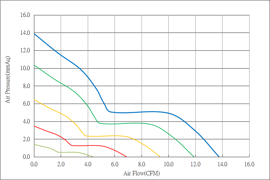
P-Q curves of a 40mm DC fan: available static pressure falls as airflow increases, so the operating point depends on system resistance.
Grilles, filters, drive cages, heat sinks, backplanes, and ducts all increase resistance. As resistance increases, the fan’s operating point moves toward lower airflow.
This is why two fans with similar free-air CFM can perform very differently inside the same server.
| Operating condition | What to compare | Main selection risk |
|---|---|---|
| Open airflow path | Airflow, power, and sound at the intended speed | Using excessive speed and power without a meaningful cooling benefit |
| Dense heat sink or drive wall | Static pressure at the required airflow | Selecting by free-air CFM and starving downstream components |
| Tandem or counter-rotating assembly | Complete assembly curve, power, depth, and controls | Treating a dual-rotor assembly like a standard single fan |
| PWM-controlled fan wall | Performance and stable feedback across the duty range | Passing a full-speed test but failing during normal speed control |
The selected fan should also provide reasonable margin for filter loading, manufacturing tolerances, changes in ambient temperature, and any required fan-failure condition.
Check Server Fan Voltage, PWM, and Feedback Signals
Mechanical fit does not guarantee electrical compatibility.
Confirm the rated voltage, startup current, full-speed running current, connector housing, pin assignment, and cable length. The PWM input requirements, FG or tachometer pulse definition, RD or alarm logic, and minimum speed expected by the BMC must also match the server platform.
The referenced YCCFAN 60mm and 80mm series include 12V, 24V, or 48V versions, depending on the exact model. Their product information also lists optional PWM, FG, or RD functions.
The exact model suffix, wiring configuration, connector, and control requirements must be confirmed before sampling. A generic four-wire connector does not prove compatibility because the pin assignment, PWM frequency, tachometer pulse count, or alarm logic may differ.
Use dimensional drawings and electrical specifications rather than relying on wire colour.
Validate the Server Cooling Fan in the Closed Chassis
Final approval requires testing in a representative, fully assembled chassis.
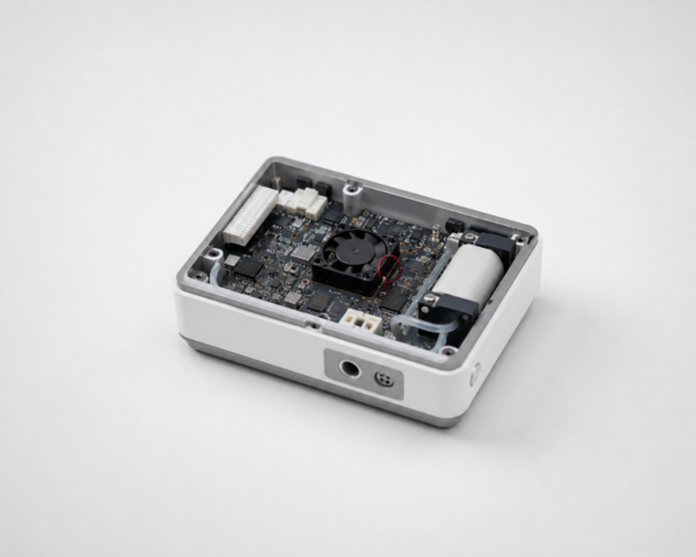
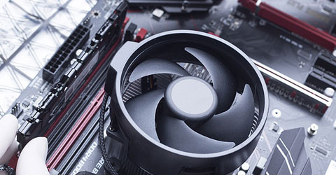
Airflow path in a compact assembly: the fan must overcome the resistance of grilles, boards, and ducts in the complete chassis.
Install the normal drive population, heat sinks, air ducts, cover, filters, guards, and other components that affect airflow. Run a representative peak workload until temperatures stabilize.
The test should record the inlet temperature and the temperatures of critical components such as the CPU, GPU, storage devices, memory, and power-related components. Fan duty, speed feedback, alarms, power consumption, and operating noise should be monitored at the same time.
If the system requires cooling redundancy, repeat the test under the specified fan-failure condition.
Testing with the chassis cover removed is not sufficient. Removing the cover changes system resistance and can allow air to bypass the intended path, producing results that do not represent normal operation.
Server Fan Size Selection Checklist
| Check | Approval criterion |
|---|---|
| Physical fit | Frame size, depth, mounting holes, guard, connector, and service clearance are compatible |
| Airflow path | No major inlet blockage, bypass leakage, or downstream dead zone is present |
| Operating point | The P-Q curve provides the required airflow at the estimated system pressure |
| Electrical compatibility | Voltage, current, pinout, connector, and cable meet platform requirements |
| Control compatibility | PWM, FG, RD, or tachometer behavior matches the BMC or controller |
| Thermal validation | Critical components pass closed-chassis testing at a representative load |
| Acoustics | Noise is acceptable at the normal operating duty rather than only at idle |
Frequently Asked Questions
What Server Fan Size Fits a 1U Server?
A 40mm fan is a common starting point for a 1U server, although 36mm and 38mm designs also exist.
Measure the usable opening and available depth, then compare fan performance at the required operating pressure. Chassis height alone cannot identify the correct fan.
Can an 80mm Server Fan Fit in a 2U Chassis?
It may fit, but sheet metal, rails, brackets, fan-wall construction, and safety clearance reduce the usable space.
Confirm the actual opening, mounting-hole pattern, frame depth, and airflow coverage before selecting an 80mm fan.
Is a 120mm Server Fan Better for a 4U System?
Not necessarily.
A 120mm fan may provide the required airflow at a lower speed in a relatively open 4U chassis. In a restrictive storage, GPU, or passive-heat-sink path, an 80mm high-pressure fan may perform better at the required operating point.
Can I Replace a Loud 1U Fan with a Quiet Fan?
Only after comparing static pressure, airflow at the expected system resistance, current, PWM response, tachometer feedback, and alarm behavior.
The replacement should also be validated in the closed chassis under a representative workload. Matching frame size or free-air CFM alone is not enough.
Does a Deeper Server Fan Always Provide More Static Pressure?
No. A deeper frame can support a pressure-oriented impeller and motor design, but depth alone does not determine performance.
Compare the published P-Q curves for the exact fan models under consideration.
Get Server Fan Selection Support
To evaluate a server cooling fan, provide the chassis height, measured fan opening, available installation depth, mounting-hole spacing, required airflow direction, rated voltage, current limit, control-signal requirements, estimated system resistance, and target airflow.
Information about the heat sinks, drive bays, filters, backplanes, and air ducts will also help identify suitable candidates.
You can contact YCCFAN with these requirements or review the broader server fan selection guide.
Before final approval, confirm the dimensional drawing, P-Q curve, complete model suffix, connector, and wiring configuration, then validate the selected fan with a representative sample in the actual chassis.