





How Much DC Fan Airflow Does an Electronics Enclosure Really Need?
Choosing a DC fan for an electronics enclosure often starts with one question: how much airflow do I actually need?
The answer should not come from enclosure size alone, and choosing the fan with the highest CFM is not necessarily the safest approach. A practical DC fan airflow calculation starts with the heat generated inside the enclosure and the maximum temperature rise the equipment can tolerate. From there, engineers still need to consider filters, vents, heat sinks, PCB density, airflow direction, and system resistance.
For forced-air enclosure cooling, a commonly used relationship calculates required airflow from internal heat dissipation and allowable temperature rise. AutomationDirect, for example, specifies fan sizing based on the watts to be dissipated and the difference between the maximum allowable enclosure temperature and maximum ambient temperature.
This means the calculated CFM is best treated as a thermal airflow requirement, not automatically as the free-air CFM that should appear on the fan label.
Key Takeaways
- Required enclosure airflow mainly depends on heat load and allowable temperature rise, not enclosure volume alone.
- A practical formula is approximately CFM = 1.76 × Watts / ΔT (°C).
- The calculated airflow is the airflow the system needs during operation, not necessarily the fan's maximum free-air rating.
- Filters, vents, heat sinks, cables, densely packed PCBs, and narrow airflow passages increase resistance and reduce actual airflow.
- Good DC fan sizing requires both a thermal calculation and evaluation of the fan's airflow-static pressure performance.
DC Fan Airflow Calculation: The Basic Formula
For a first-pass electronics enclosure airflow calculation, use:
Required Airflow (CFM) ≈ 1.76 × Heat Load (W) ÷ Allowable Temperature Rise (°C)
Or in metric units:
Required Airflow (m³/h) ≈ 3.0 × Heat Load (W) ÷ Allowable Temperature Rise (°C)
Where:
- Heat Load (W) = heat that must be removed from inside the enclosure
- Allowable Temperature Rise (ΔT) = maximum acceptable internal air temperature minus inlet ambient temperature
- CFM = cubic feet of air per minute
The equivalent Fahrenheit-based formula is approximately:
CFM = 3.17 × Watts ÷ ΔT (°F)
This is consistent with established enclosure fan-sizing guidance. The equation also shows why simply asking for a "100 CFM fan" without defining the heat load and temperature target provides very little engineering information.
Quick Airflow Reference for a 100 W Heat Load
| Allowable Temperature Rise | Approx. Required Airflow |
|---|---|
| 5°C | 35.2 CFM |
| 10°C | 17.6 CFM |
| 15°C | 11.7 CFM |
| 20°C | 8.8 CFM |
A tighter temperature limit requires more airflow. If the electronics can safely tolerate a larger temperature rise above ambient, the required airflow decreases.
Step 1: Calculate the Heat That Actually Needs to Be Removed
Before doing a cooling fan CFM calculation, identify the enclosure's internal heat load. Do not automatically add the rated input wattage of every component unless that power actually becomes heat inside the enclosure.
Useful sources include: component power-loss specifications; power supply efficiency and losses; inverter or converter losses; processors, GPUs, FPGAs and power semiconductors; transformers and inductors; drives and control modules; communication equipment; other heat-producing electronics.
When manufacturer heat-loss data is available, it is usually more useful than simply using the component's maximum electrical rating.
For example, suppose an enclosure contains: power supply losses 35 W; control electronics 20 W; processing board 45 W; power module losses 20 W. The approximate internal heat load is:
35 + 20 + 45 + 20 = 120 W
That 120 W is the starting point for the airflow calculation.
Step 2: Define the Allowable Temperature Rise
The next variable is ΔT. Suppose worst-case inlet ambient temperature = 35°C and desired maximum enclosure air temperature = 45°C. Then:
ΔT = 45°C − 35°C = 10°C
Do not confuse maximum component junction temperature with the enclosure air temperature target. A semiconductor may have a much higher absolute temperature rating, but nearby capacitors, batteries, connectors, power supplies, or other components may establish a lower practical system limit. The correct ΔT should therefore be based on the thermal limits of the complete equipment design.
Step 3: Calculate the Required Fan Airflow
Using the previous example: Heat load = 120 W; Allowable temperature rise = 10°C. The enclosure cooling formula gives:
Required airflow = 1.76 × 120 ÷ 10 = 21.1 CFM
So the enclosure needs approximately 21 CFM of effective airflow under the assumed thermal conditions. This does not mean that selecting any fan labeled "21 CFM" will necessarily solve the problem. That distinction is one of the most important parts of DC fan selection.
Why a 21 CFM Calculation Does Not Mean You Should Buy a 21 CFM Fan
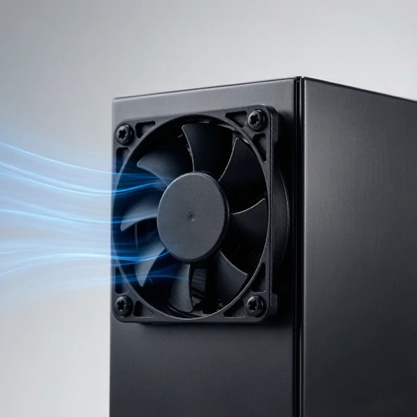
Fan datasheets commonly show maximum airflow under low-resistance or free-air conditions. Once the fan is installed inside real equipment, airflow can decrease. An enclosure may include intake grilles, dust filters, perforated panels, finger guards, heat sinks, tightly packed PCBs, cables, ducts, narrow passages, and restricted exhaust openings. Each restriction adds resistance to airflow.
As static pressure increases, the amount of air delivered by a fan generally decreases. Oriental Motor illustrates this using an electronics enclosure: a relatively open system allows higher airflow, while restricted outlets and dense internal structures increase resistance and reduce the airflow the fan can actually deliver. That is why required fan airflow and rated maximum airflow should not be treated as the same number.
The thermal calculation answers: how much air must move through the enclosure? The fan performance data answers: can this particular fan still move that much air against the resistance of my enclosure? Both questions have to be answered.
When shortlisting candidates, filter DC cooling fans by airflow and check each model’s P-Q curve at the real operating point instead of comparing maximum CFM.
Check the Fan Curve Instead of Comparing Maximum CFM Alone
Once the minimum airflow requirement is known, compare candidate fans under the expected pressure resistance of the system. A fan with a higher free-air CFM can sometimes deliver less useful airflow than another fan when both are installed behind a restrictive filter or inside a densely packed enclosure.
YCCFAN's own selection guidance similarly distinguishes relatively open airflow paths, where axial and centrifugal cooling fans are commonly appropriate, from more restrictive airflow paths where higher-pressure centrifugal designs may be considered. For an ordinary electronic enclosure with a reasonably open inlet, outlet, and internal path, an axial DC fan may provide an efficient solution. As restrictions increase, static-pressure capability becomes increasingly important.
The important engineering point is simple: select the fan for the airflow it can deliver in the system—not only the largest CFM number in the specification table. For a deeper look at how operating point and pressure interact, see how to read a DC blower fan curve.
How Filters and Vents Change the Airflow Requirement
Filters are especially easy to overlook during DC fan sizing. A clean filter creates resistance. As dust accumulates, that resistance can increase further. Small perforations, decorative grilles, or undersized exhaust openings can produce a similar effect. You should therefore review: intake opening area; exhaust opening area; filter pressure drop; grille or guard restrictions; internal component density; distance and direction between inlet and outlet.
Avoid designing an enclosure in which a large fan tries to move air through a very small outlet. A restricted outlet raises system resistance and moves the fan away from its maximum-airflow condition. If a filter is required, evaluate the fan with the filter included in the airflow path rather than calculating the filter and fan independently.
Do You Need to Add a Safety Margin to the CFM Calculation?
Usually, some design margin is sensible because the first calculation cannot perfectly represent every real operating condition. However, applying the same arbitrary multiplier to every project is not a substitute for engineering evaluation. Consider uncertainty from: component power variation; higher-than-expected ambient temperature; filter loading; manufacturing tolerances; vent resistance; cable routing; future component changes; aging or contamination.
For example, the previous 120 W calculation produced approximately 21.1 CFM. If an early prototype design temporarily uses a 25% airflow margin:
21.1 × 1.25 ≈ 26.4 CFM
That can provide a useful initial selection target, but the final fan should still be checked against its airflow-static pressure curve and verified in the real enclosure. A fan that delivers 30 CFM in free air but only 18 CFM after installation would still be inadequate for a system requiring roughly 21 CFM.
Airflow Quantity Cannot Fix a Bad Airflow Path
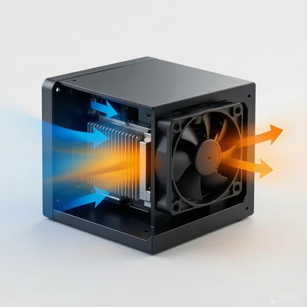
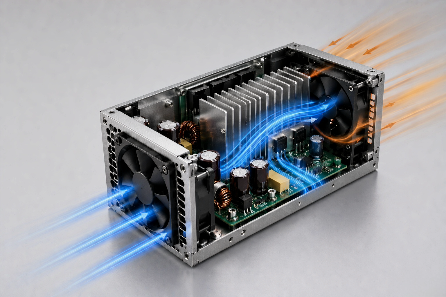
Even a correct DC fan airflow calculation can lead to poor cooling if the air bypasses the components that actually need it. Consider an enclosure with a 30 CFM fan. If most incoming air immediately travels from an inlet to a nearby exhaust opening, the enclosure may technically have substantial airflow while a power device on the opposite side remains in a stagnant hot zone. The airflow path should encourage cool incoming air to travel through or across the primary heat-generating regions before it exits.
PCB and Component Placement
Large circuit boards can behave like walls inside an enclosure. High installation density leaves less space for air to pass, increasing system resistance.
Heat Sink Orientation
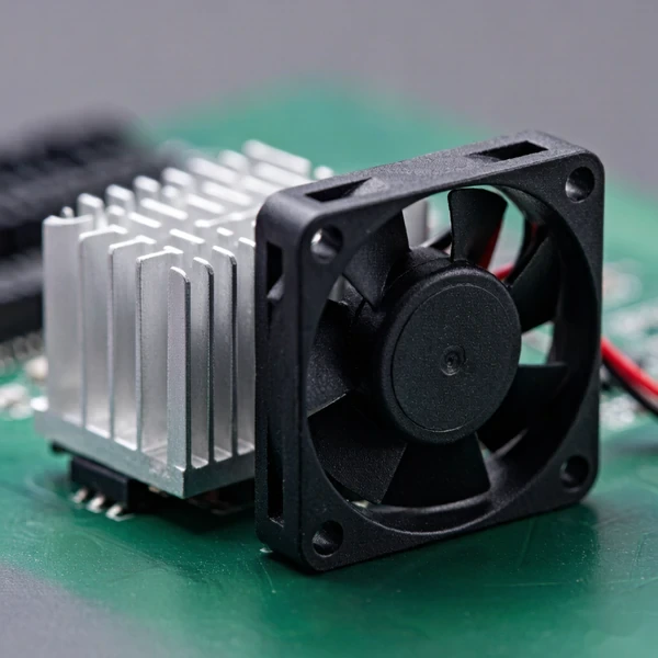
Air should pass effectively through heat-sink fins rather than striking a blocked side or bypassing the heat sink.
Fan-to-Component Distance
A nearby fan does not automatically guarantee effective cooling. Air distribution and local velocity around the heat source matter.
Inlet and Exhaust Placement
Place openings so that air is encouraged to sweep through the enclosure instead of taking the shortest low-resistance path directly from fan to vent.
Internal Hotspots
The bulk enclosure temperature can be acceptable while an individual power component remains too hot. Thermal testing should therefore include critical component temperatures, not only inlet and exhaust air temperatures.
Should the Fan Push Air In or Pull Hot Air Out?
Both arrangements can work. The better choice depends on enclosure structure, contamination requirements, fan location, and the desired airflow path. An intake fan can help direct cooler ambient air toward heat-generating components. A filtered intake arrangement may also be useful when controlling the path through which outside air enters the equipment. An exhaust configuration can be effective when the enclosure already provides a clear low-resistance intake path and the objective is to remove heated internal air. Instead of deciding based only on "push versus pull," ask: does the configuration create a controlled airflow path through the components that need cooling?
A Practical DC Fan Sizing Workflow
For most electronics projects, use the following sequence:
- Determine the worst-case heat load. Add the heat that must actually be dissipated inside the enclosure.
- Determine maximum inlet temperature. Use realistic worst-case ambient conditions around the equipment.
- Set the maximum acceptable internal temperature. Base this on the system's thermal limits rather than a single component's maximum rating.
- Calculate ΔT: ΔT = Maximum internal temperature − Maximum inlet ambient temperature.
- Calculate baseline airflow: CFM ≈ 1.76 × W ÷ ΔT°C.
- Review airflow restrictions. Account for filters, grilles, heat sinks, dense PCBs, cables and narrow vents.
- Review airflow-static pressure performance. Confirm that the selected fan can deliver the required airflow under system resistance.
- Check mechanical and electrical constraints. Confirm fan dimensions, thickness, mounting position, supply voltage, current, noise target, connector, and control or monitoring requirements such as 2-wire, 3-wire, and 4-wire DC fans with FG, RD, or PWM signals.
- Build and test the real enclosure. Measure temperatures at critical components under worst-case load and ambient conditions.
- Adjust the design if necessary. Changing the fan is only one option. Vent area, heat-sink orientation, component position, ducting, baffles, or airflow direction can sometimes solve a thermal problem more efficiently than simply increasing fan speed.
When More CFM Is Not the Right Solution
If testing shows excessive temperature, increasing airflow may help—but not always. A higher-CFM fan may produce limited improvement when: the exhaust opening is too restrictive; the filter creates excessive pressure drop; a PCB blocks the airflow path; air bypasses the main heat source; the heat sink is poorly oriented; hot exhaust air is recirculated into the intake; ambient temperature is already close to the required internal temperature.
Forced ventilation relies on ambient air as the cooling medium. It cannot make the enclosure air colder than the incoming ambient air through airflow alone. If outside air cannot be introduced because of water, dust, chemicals, or environmental sealing requirements, or if the required internal temperature is below ambient, a different thermal-management approach may be necessary.
Matching the Calculation to a Real DC Fan
After the calculation is complete, the final step is matching airflow demand to a practical fan platform. YCCFAN currently offers DC cooling fans in sizes ranging from compact 20 mm designs to models around 250 mm, with common DC voltage configurations including 5 V, 12 V, 24 V, and 48 V. Its published product and customization information also covers airflow, static pressure, speed, noise, connector, FG, RD, and PWM requirements for different equipment designs.
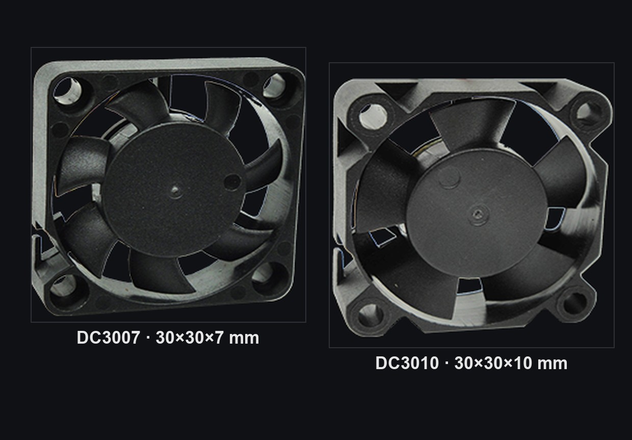
For example, compact YCCFAN models illustrate why airflow and pressure have to be considered together. The 25 × 25 × 7 mm DC2507 is listed at up to 3.09 CFM and 6.39 mmH₂O static pressure, while the larger 40 × 40 × 7 mm DC4007 reaches up to 6.49 CFM with a different pressure profile. They are designed for different space and airflow requirements rather than simply representing a "better" and "worse" fan.
For an OEM enclosure, inverter, power supply, communication device, control system, or other electronic product, useful selection information includes: internal heat load in watts; maximum ambient temperature; maximum acceptable internal temperature; required airflow; estimated system resistance; available fan dimensions; DC supply voltage; noise requirement; filter or grille structure; required FG, RD, or PWM functions. Providing these parameters is much more useful than requesting a fan by CFM alone.
FAQ
How do I calculate CFM for an electronics enclosure?
A practical starting formula is: CFM ≈ 1.76 × heat load in watts ÷ allowable temperature rise in °C. For example, 200 W of internal heat with a 10°C allowable temperature rise requires approximately 35.2 CFM of effective airflow. The selected fan must still be checked under the enclosure's actual airflow resistance.
Is enclosure volume needed for DC fan airflow calculation?
Not for the basic heat-removal calculation. Heat load and allowable temperature rise are the primary inputs. Enclosure dimensions still matter because they influence vent area, component density, airflow distribution and system resistance. Air-changes-per-minute can describe how frequently enclosure air is replaced, but it does not directly determine whether enough heat is being removed.
Should I choose a fan with higher CFM than the calculated requirement?
The fan should be capable of delivering at least the required airflow after installation losses are considered. Do not simply choose a free-air CFM rating equal to the calculated value. Evaluate the fan's airflow-static pressure performance and then validate the design in the actual enclosure.
Final Takeaway
A reliable DC fan airflow calculation begins with heat:
Required CFM ≈ 1.76 × Heat Load (W) ÷ Allowable Temperature Rise (°C)
But that number is only the first step. Effective electronics cooling depends on three connected factors: thermal requirement + system resistance + airflow path. Calculate how much airflow the enclosure needs, determine how much resistance the real structure creates, select a fan that can deliver the required airflow at that resistance, and then verify the result under realistic thermal conditions. That approach produces a much more reliable cooling design than selecting a DC fan based on maximum CFM alone.
Browse DC fans for electronics enclosures and match CFM to your actual heat load with a safety margin.