





PWM Frequency and Duty Cycle for DC Fans: How to Avoid Noise and Unstable Speed
PWM gives a DC fan precise speed control without constantly changing its supply voltage. Problems usually start when the control method, frequency, duty cycle, or fan interface does not match.
A fan may stay at full speed regardless of the command. At low speed, it may buzz, repeatedly accelerate and slow down, or stop altogether. Those symptoms are often blamed on the motor or bearing, although the control signal may be the real cause.
With PWM fan control, frequency and duty cycle do different jobs. Frequency defines how often the PWM signal repeats. Duty cycle represents the speed command. A dedicated 4-wire PWM input also works differently from switching the fan's supply power on and off.
Once these three points are clear, most PWM-related problems become easier to trace.
What PWM Fan Control Actually Means
There is more than one way to reduce the speed of a DC fan.
A simple 2-wire fan has power and ground. Some models can be slowed by reducing the supply voltage, provided they remain within the permitted operating range.
A 3-wire fan adds an FG or tachometer signal for speed feedback. Speed control, however, may still depend on the supply voltage.
A typical 4-wire fan adds a separate PWM input. The fan continues receiving its normal DC supply, while the PWM line tells the internal controller how fast it should run.
A common 4 wire fan control arrangement looks like this:
| Connection | Function |
|---|---|
| Ground | Electrical reference |
| Power | Continuous DC supply |
| FG / Tach | Speed feedback |
| PWM | Speed-control command |
Pin order and wire color are not universal. They should be checked against the fan datasheet rather than guessed from appearance.
YCCFAN's DC fan wiring guidance also separates power, FG/RD feedback and PWM functions, which is useful when comparing 2-wire, 3-wire and 4-wire fans.
For a fan with a dedicated PWM input, the power supply normally remains separate from the speed-control signal unless the manufacturer specifies another method.
PWM Frequency and Duty Cycle Affect Different Things
PWM is a repeating digital signal described mainly by frequency and duty cycle.
Frequency tells you how many times the PWM cycle repeats each second. A 25 kHz PWM signal repeats 25,000 times per second, so one cycle lasts about 40 microseconds.
Duty cycle tells you how much of that cycle stays active. At 50% duty, the signal is active for roughly half of each period. At 25%, it is active for one quarter.
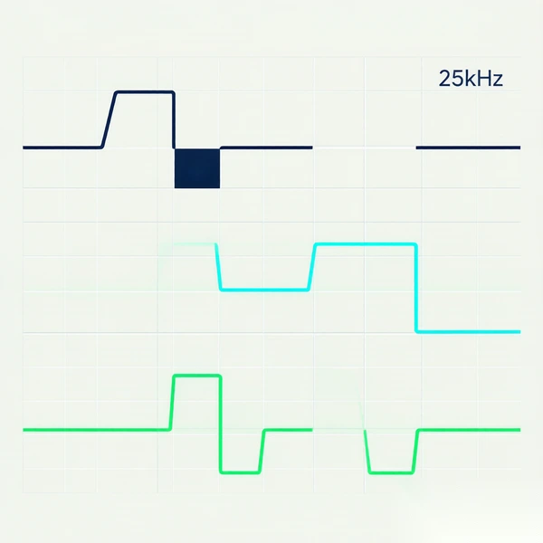
During normal fan speed control, frequency is usually kept at the value required by the fan. Speed is changed by adjusting duty cycle.
So lowering a fan from full speed to half speed is normally not done by changing a 25 kHz signal to 12.5 kHz. The frequency stays where the fan expects it, while the duty command changes.
For DC fan speed control, this is a useful distinction to keep in mind: frequency belongs to the interface; duty cycle belongs to the speed request.
What DC Fan PWM Frequency Should You Use?
The correct DC fan PWM frequency comes from the fan specification.
For many Intel-style 4-wire PWM fans, approximately 25 kHz is a common reference. Noctua, for example, specifies a 21–28 kHz range for its compatible 4-wire implementation, with 25 kHz as the target.
That figure should not automatically be copied to every industrial DC fan. Different product families can have different PWM input requirements.
This becomes relevant when a fan is connected directly to a microcontroller. Many controllers generate default PWM signals at only a few hundred hertz or several kilohertz. The waveform can look perfectly clean on an oscilloscope and still be unsuitable for the fan.
An out-of-range frequency may show up as incorrect RPM, a narrow speed-control range, full-speed operation, unexpected stopping, speed fluctuation, or tonal noise.
If a newly connected PWM fan behaves strangely, checking the actual output frequency is usually more useful than immediately changing the fan curve in software.
How PWM Duty Cycle Actually Changes Fan Speed
Duty cycle is the value normally used to request more or less speed. It should not, however, be read as a direct RPM percentage.
A 50% command does not necessarily produce exactly 50% of maximum fan speed.
The response depends on the fan's internal controller. Some models are fairly linear through most of their control range. Others hold a minimum speed for part of the lower range and then increase more rapidly.
Two fans can even share the same maximum RPM and still run at different speeds when both receive a 60% command.
For that reason, an equation such as:
RPM = maximum RPM × duty cycle
is only an approximation unless the fan's own characteristic confirms it.
Where speed accuracy matters, actual FG or tachometer feedback is more useful than estimating RPM from the command alone.
YCCFAN’s PWM-controlled DC fans support wide PWM frequency ranges and hold speed stable across the usable duty cycle.
What Happens at Low Duty Cycle
The lower end of the PWM range is where a lot of real-world problems appear.
A fan may behave normally at 60%, 40% and 30%, then start fluctuating at 15%. Another model may remain stable at a very low command but stop when PWM reaches 0%.
There is no universal response.
Some fans settle at a minimum RPM. Some stop. Some become unstable below a certain command. The manufacturer's PWM characteristic should therefore be treated as the usable control range rather than assuming that every value between 0% and 100% behaves equally well.
Startup adds another complication.
A fan that can keep rotating at a low PWM command may need a higher command to start from rest. If a controller sends only the low running value after the fan has stopped, the rotor may twitch or fail to begin turning.
In equipment that operates close to the fan's minimum speed, it is worth checking both values separately: the lowest stable running duty and the lowest reliable starting duty.
FG feedback is useful here. The controller can confirm that the fan has actually started instead of assuming that a valid PWM signal automatically means rotation.
Why PWM Fans Become Noisy or Unstable
Not every sound heard during PWM operation is caused by the PWM signal itself.
If the noise follows RPM, the source may be aerodynamic or mechanical. Blade-passing sound, enclosure resonance, bearing noise and turbulence all change with rotational speed.
A different situation occurs when a new buzz or tonal sound appears only after PWM control is introduced. Then the frequency, low-duty behavior and electrical interface deserve attention.
Simply pushing the PWM frequency higher is not a reliable fix for PWM fan noise. The fan still has an approved control range. Moving outside that range to escape one sound can introduce poor speed response instead.
One practical test is to keep frequency fixed and vary the duty cycle. If the sound moves with fan RPM, the cause is more likely connected to the rotating system or airflow. If similar RPM can be maintained while changes in PWM frequency noticeably change the sound, the control interface should be checked more closely.
Low-duty instability often produces another familiar symptom: RPM hunting.
Sometimes the fan is doing exactly what the controller tells it to do. A temperature rises slightly, the software raises fan speed sharply, the component cools quickly, and the command immediately drops again. The temperature rises once more and the cycle repeats.
The fan then sounds unstable even though its response is correct.
In that case, the thermal control logic may need more hysteresis, slower transitions or a smoother relationship between temperature and PWM duty.
If the PWM command remains steady while RPM continues moving up and down, attention should shift back to the fan's low-speed operating range, power stability and control-signal compatibility.
Why a 4-Wire PWM Fan Sometimes Runs at Full Speed
A fan that stays at maximum RPM regardless of the command usually points to the control interface.
The PWM wire may not actually be receiving a valid signal. Some 4-wire fans are designed to default to full speed when the PWM input is missing, so an open or incorrectly connected control lead can look like a failed fan controller.
The operating mode is also worth checking. A board that supports both voltage control and PWM may have been configured for the wrong mode.
Frequency can cause the same symptom. A controller may report 30%, 50% or 70% duty while the fan does not recognize the waveform correctly.
Separate power supplies can create another problem if the controller and fan do not share the required signal reference. Depending on the interface, the output stage itself may also need to meet an open-collector or open-drain requirement.
The PWM lead is a control input, not the motor's main power connection. Its accepted logic voltage should come from the fan specification rather than from the fan's 12 V or 24 V supply rating.
For a fan that remains at full speed, it is usually enough to work through the signal path in order: confirm the PWM connection, controller mode, frequency, ground reference and electrical output type.
How to Check PWM Fan Control in Practice
A bench test does not need to be complicated.
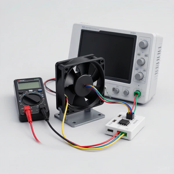
Start with the fan at its rated supply voltage and use the specified PWM frequency. Run it at full duty and record RPM. Then lower the duty gradually and watch how the fan responds.
The aim is to find the point where low-speed operation stops being stable rather than forcing the fan through every possible percentage.
Once that point is known, stop the fan and try starting it from the same low command. If it cannot restart reliably, the controller needs a higher startup value even though the lower duty may still be suitable for running.
Behavior at 0% should also be checked. Some fans stop, while others remain at a defined minimum speed.
A simple record is enough:
| PWM Duty | RPM | Starts From Stop? | Noise / Stability |
|---|---|---|---|
| 100% | Measure | Yes | Check |
| 75% | Measure | Yes | Check |
| 50% | Measure | Yes | Check |
| 25% | Measure | Test | Check |
| Minimum target | Measure | Test | Check |
| 0% | Measure | Model dependent | Check |
The test becomes more useful when RPM is measured instead of judged by sound alone.
For equipment with temperature-based control, repeat the check after the fan is installed in the complete system. A fan can behave perfectly during a fixed-duty bench test and still become annoying if the finished controller changes speed too frequently.
Selecting a DC Fan When PWM Is Part of the Design
PWM capability is better considered during fan selection rather than added after the airflow and static-pressure decisions have already been made.
A fan can meet the cooling requirement and still be a poor match if its controllable speed range does not fit the application's acoustic target or if its PWM input is incompatible with the controller.
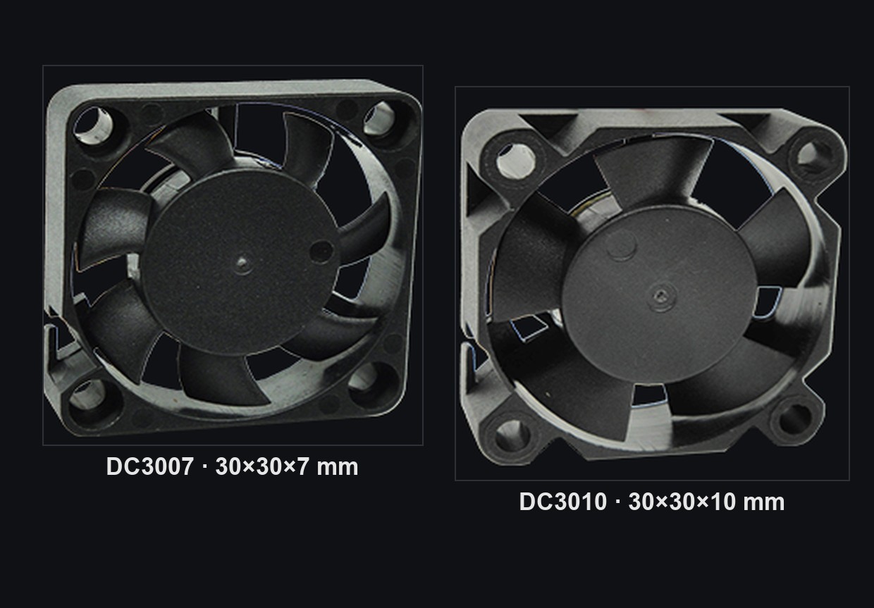
YCCFAN offers DC fan models with PWM together with optional FG and RD functions. For example, the DC3010 series can be configured for variable-speed cooling applications that also require operating feedback.
For this type of project, the mechanical cooling requirement and the control requirement should be reviewed together. Airflow and static pressure still matter, but so do the supported PWM frequency, usable speed range, startup response, 0% behavior, FG/RD functions and connector definition.
That avoids reaching the prototype stage with a fan that cools correctly at full speed but cannot be controlled the way the product requires.
FAQ
What PWM frequency should I use for a 4-wire DC fan?
Use the PWM frequency stated in the fan specification.
Around 25 kHz is common for Intel-style 4-wire fans. Noctua, for example, specifies a 21–28 kHz range for its compatible designs.
Industrial fans may use different requirements, so 25 kHz should not be treated as a universal value.
Does 50% PWM duty cycle mean 50% fan speed?
No. The duty cycle is a control command, not a guaranteed RPM percentage.
The actual PWM duty cycle fan speed relationship depends on the fan's internal controller and characteristic curve. FG feedback is preferable when actual speed needs to be monitored accurately.
Why does my PWM fan become unstable at low duty cycle?
The command may be below the fan's stable controllable range.
At very low duty, a fan may hold minimum speed, fluctuate or stop. The lowest running duty can also be lower than the value required to start the fan from rest.
Check both startup and low-speed behavior for the specific fan model.
Why is my 4-wire PWM fan always running at full speed?
Check the PWM connection, controller mode, frequency, ground reference and output type.
Some 4-wire fans intentionally run at full speed when there is no valid PWM input, so full RPM does not automatically indicate a faulty fan.
Final Takeaway
Reliable PWM fan control starts with matching the controller to the fan's actual PWM specification.
Frequency normally stays within the fan's required input range, while duty cycle is used to change the speed command. Duty cycle should not be treated as a direct RPM percentage, particularly near the lower end of the fan's operating range.
Low-speed testing matters because a fan may have different limits for stable running and starting from rest.
When noise, RPM fluctuation or permanent full-speed operation appears, checking the control signal often reveals more than replacing the fan. Once the PWM interface, usable duty range and feedback behavior are known, fan speed control becomes much easier to predict in the finished cooling system.
Compare DC fans with PWM speed control and check the supported frequency range against your controller before committing.